Drake DA Series Distribution Amplifiers User Manual
Page 5
Programmable Reverse Path Step Attenuator
5
DRAKE MODELS DA100032, DA100042, DA7533, DA7543,
DA8632, and DA8642
These amplifiers are very versatile in regard to reverse (return)
path options.
If no return path is desired, remove jumpers J1, J2, and J3. These
may be stored inside the amplifier by plugging them into just a
single pin of the headers so that the one pin holds the jumper
mechanically but no electrical connection is made to other pins.
If a passive return path is required with or without attenuation, set
jumpers J1 and J3 to the passive return path settings. Leave
jumper J2 disconnected. The REVERSE PATH GAIN adjustable
attenuator may be used to set up to approximately 12 dB of
attenuation in this path, if needed. At maximum gain setting, the
insertion loss of the passive return will be nominally 1 dB. The
programmable reverse attenuator jumpers have no effect when
using the passive return path.
When gain must be added to the reverse path, set jumpers J1, J2,
and J3 to the active return path settings. This revision of the Drake
DA series of distribution amplifiers now provides a programmable
reverse step attenuator that is programmable in steps of 2 dB
between 2 dB and 30 dB. This attenuator is located electrically
after the first stage of gain in the active reverse path amplifier. This
allows a low noise figure and excellent carrier to noise ratio to be
maintained even at low reverse gain settings. The use of this
attenuator will be equivalent to using fixed output attenuators in
other commonly used amplifiers. Fine adjustment of the reverse
path gain can be accomplished using the variable REVERSE
PATH GAIN adjustment.
Set the gain using a combination of the programmable reverse
path step attenuator and the variable reverse path gain input
attenuator. Maximum reverse path gain is nominally 22 dB.
For reverse input signal levels around 15 dBmV or below, program
most of the needed attenuation using the programmable 2 dB step
attenuator and then fine tune the final dB or two using the variable
reverse path gain adjustment. If input levels are above 20 dBmV, it
is desirable to obtain as much of the needed attenuation as
possible, up to 10 dB, with the variable attenuator and then use the
step attenuator to obtain the rest.
PROGRAMMABLE REVERSE STEP ATTENUATOR SETTINGS
There are four internal jumpers used to set the programmable
reverse attenuation. Each jumper controls an attenuator. The four
attenuator values are 2 dB, 4 dB, 8 dB, and 16 dB. The total
attenuation is the sum of any attenuators that have jumpers set to
the ‘IN’ setting. When a jumper is set to the ‘OUT’ setting, that
attenuator is out of the circuit and is effectively set to 0 dB. With all
four programmable attenuators OUT and the REVERSE PATH
GAIN, variable input attenuator set to maximum gain, the active
reverse path gain is nominally 22 dB.
.
EXAMPLES
EXAMPLE 1
Assume that a particular installation requires a reverse path gain of
5 dB. Subtracting 5 from the nominal gain of 22 dB gives a result of
17 dB attenuation required to reduce the reverse path gain to 5 dB.
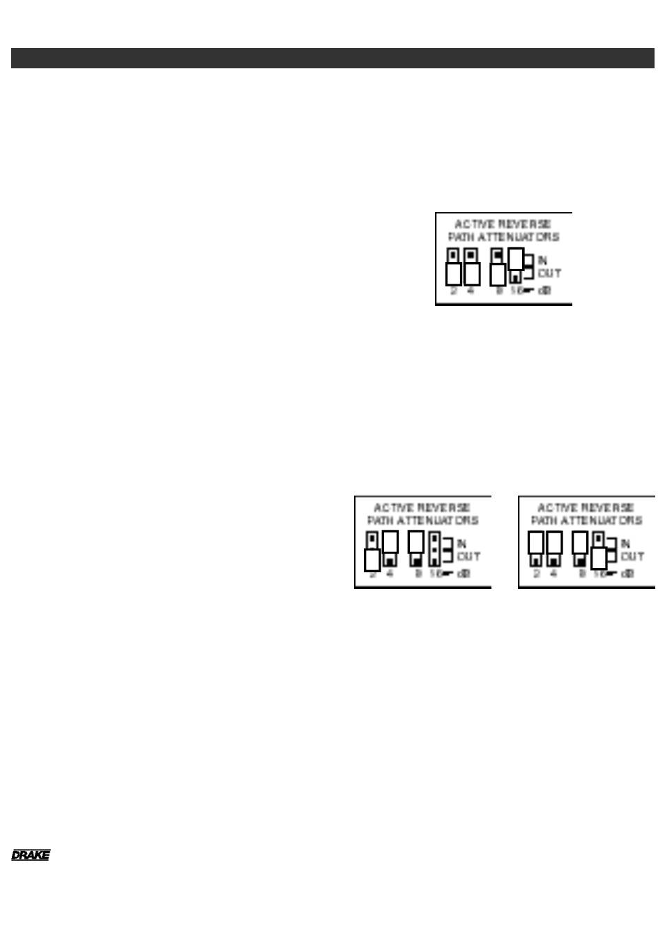
To reduce the reverse path gain by 17 dB, move the 16 dB
programmable attenuator jumper to the IN position. Then adjust the
REVERSE PATH GAIN adjustment counterclockwise to obtain the
additional 1 dB of attenuation.
(Jumper at the "16 dB" "IN" position)
EXAMPLE 2
Assume that an installation requires 15 dB of gain reduction in the
reverse path amplifier to achieve a gain of 7 dB. The step attenua-
tor can be programmed for 12 dB (setting the 8 dB and 4 dB
jumpers both to ‘IN’) or to 14 dB (setting the 8 dB, 4 dB, and 2 dB
jumpers all to ‘IN’) and then adjusting the variable REVERSE
PATH GAIN control to reduce the gain the additional 1 or 3 dB. The
idea here is that one should set the step attenuator slightly less
than the attenuation needed so that there can always be some fine
adjustment of the variable gain control.
(Jumpers at the
(Jumpers at the
"4 db" and "8 dB" "IN" positions)
"2 dB", "4 dB",
and "8 dB" "IN" positions)
SUMMARY
If reverse input levels are low, in the 0 dBmV area, use as little
attenuation at the reverse path gain input attenuator as possible.
This will maintain the best possible C/N ratio by keeping the
reverse path amplifier noise figure low. Obtain most gain reduction
of the reverse path amp by using the step attenuator. On the other
hand, if reverse input levels are high, say around 20 dBmV, you
can safely dial in 10 dB to 12 dB of attenuation with the input gain
adjustment without degrading the C/N. This will keep distortion
products low. Obtain the rest of the attenuation with the step
attenuator.
P/N: 3852703 rev L-10-09
R.L.
DRAKE Holdings, LLC
Springboro, OHIO 45066 U.S.A
© Copyright 2009 R.L. Drake
® is a registered trademark of R.L. Drake
Holdings, LLC