Implementation – Quantum Composers 9732 Parallel Configuration User Manual
Page 2
Implementation:
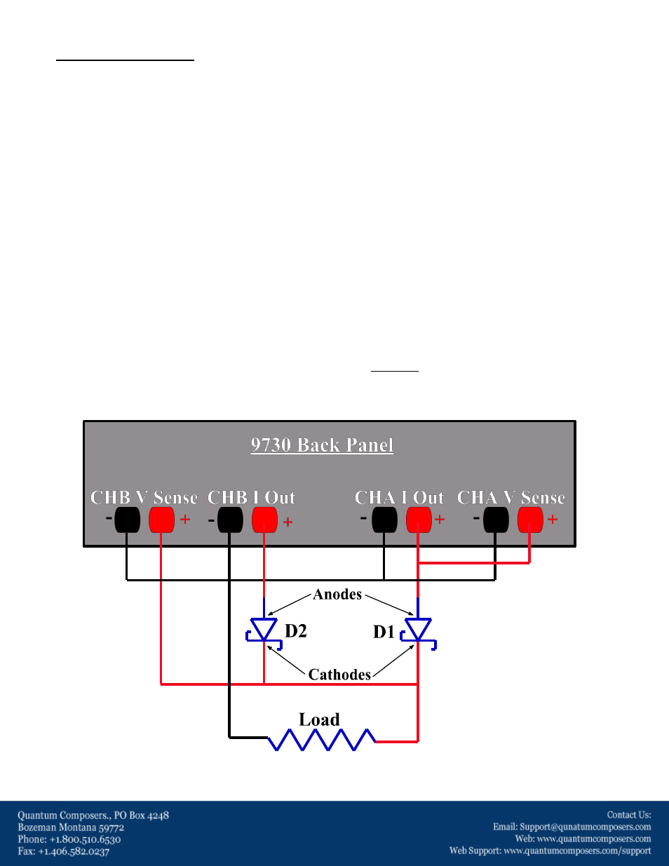
The figure shown below represents the recommended wiring to achieve the parallel configuration. Note that the
blocking diodes are placed immediately at the output on each channel’s positive terminal. To prevent damage to
the 9732, it is EXTREMLY important that the anodes of both diodes be connected to the positive channel
terminals (shown below). Refer to the following list of suggested diodes to use in this configuration:
Suggested Diodes Used at D1 & D2:
-On Semiconductor: MBRB4030T4G
-STMicroelectronics: STPS30M60ST
-Vishay: VT4045BP-M3/4W
Voltage Monitors:
As seen below, the voltage monitors of either channel may be placed before or after the blocking diodes,
depending on what measurements are required. If the voltage prior to the diodes is to be monitored, connect
the positive voltage monitor to the anode of the corresponding blocking diode. If the voltage at the load is to be
monitored, connect the positive voltage monitor as close to the load as possible. Connecting the voltage
monitors as shown below allows one to monitor both the voltage across the load as well as the inherent voltage
drop across the blocking diodes.
Current Monitors:
The current monitors on each channel represent each channel’s individual current. The total current through the
load can simply be measured as the summation of the two current monitor signals.
Figure 3 – Parallel Configuration Wiring