LowFlow 8000 Series Control Valve User Manual
I & m 8000 series, Ideal installation schematic, Preferred installation
3170 Wasson Road • Cincinnati, OH 45209 USA
Phone 513-533-5600 • Fax 513-871-0105
[email protected] • www.lowflowvalve.com
I & M 8000 Series
Installation & Maintenance Instructions for
8000 Series Low Flow Control Valves
Warning:
Low Flow Regulators must only be used, installed and repaired in accordance with these Installation & Main-
tenance Instructions. Observe all applicable public and company codes and regulations. In the event of leakage or
other malfunction, call a qualified service person; continued operation may cause system failure or a general hazard.
Before servicing any valve, disconnect, shut off, or bypass all pressurized fluid. Before disassembling a valve, be sure
to release all spring tension.
Please read these instructions carefully!
Your LowFlow/Jordan product will provide you with long,
trouble-free service if it is correctly installed and main-
tained. Spending a few minutes now reading these in-
structions can save hours of trouble and downtime later.
When making repairs, use only genuine LowFlow Valve
parts, available for immediate shipment from the factory.
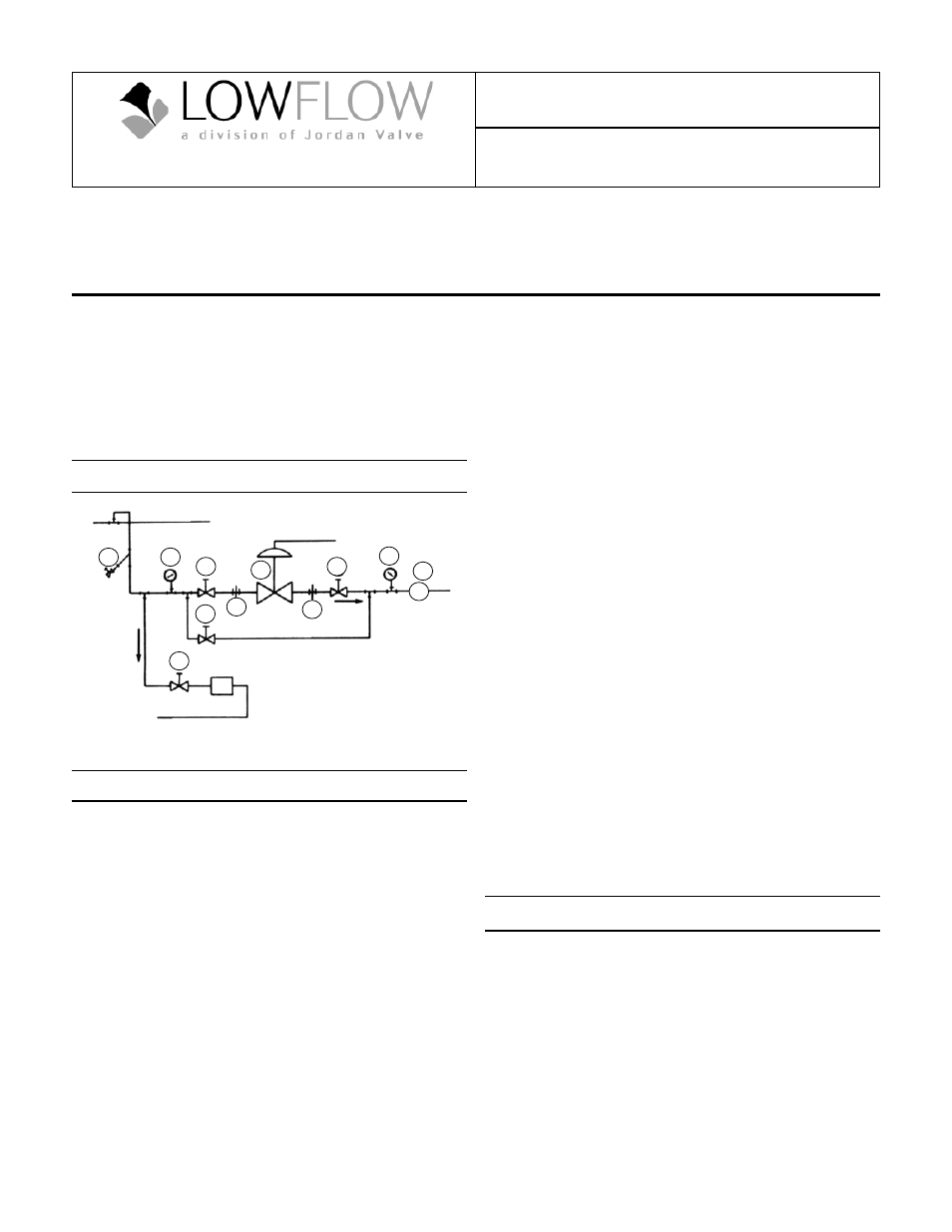
Ideal Installation Schematic
Main Line
Bypass Line
1. Shut-off valve
2. Pipe union
3. Strainer/drainer valve
4. Pressure gauge
5. Jordan Series 708 DCV
6. Relief valve
Steam
Trap
Condensate Return
3
4
4
1
1
1
1
2
1
5
6
R
Preferred Installation
1.
To control very low flow rates, Mark 8000 control
valves are often provided with trims having very
small clearances. To keep this trim functioning prop-
erly, it is essential that the fluid flowing through the
valve be clean.
2.
To protect the valve from grit, scale, thread chips
and other foreign matter, ALL pipelines and piping
components should be blown out and thoroughly
cleaned before the installation process begins.
3.
Shutoff valves, pressure gauges, and by-pass pip-
ing should be installed as indicated in the Ideal In-
stallation Schematic to provide easier adjustment,
operation and testing.
4.
A line strainer should be installed on the inlet side
of the valve to protect it from grit, scale, and other
foreign matter. A 0.033 perforated screen is usually
suitable for this purpose. Line strainers are available
from Jordan Valve.
5.
For best control, 3'-0" straight sections of pipe should
be installed on either side of the valve.
6.
In preparing threaded pipe connections, care
should be exercised to prevent pipe-sealing com-
pound from getting into pipelines. Pipe sealing com-
pound should be used sparingly, leaving the two
end threads clean. Jordan Valve uses, and recom-
mends, thread sealer Teflon ribbon.
7.
The flow arrow on the valve body must be pointed
in the direction of the flow. Ideally the valve should
be installed in the highest horizontal line of piping to
provide drainage for inlet and outlet piping, to pre-
vent water hammer, and to obtain faster response.
8.
If possible, install a relief valve downstream from the
valve. Set at 15 psi above the control point of the
valve.
9.
In hot vapor lines, upstream and downstream pip-
ing near the valve should be insulated to minimize
condensation.
10. Evaluate inlet and outlet pipe friction losses and ve-
locities to decide when smaller outlet piping might
cause excessive back pressure. When required, a
standard tapered expander connected to the outlet
of the valve is recommended.
11. When surges are severe, a pipe accumulator is rec-
ommended.
12. On steam control applications, install a steam trap
with sufficient capacity to drain the coil or condens-
er. Be sure to have a good fall to the trap, and no
backpressure. Best control is maintained if the coil
or condenser is kept dry.
Trouble Shooting
If You Experience Erratic Control:
•
Oversizing can cause cycling or hunting, recalcu-
late the size required
•
Undersizing can cause the control point to drop off
under peak loads, increase the trim size
•
Inlet pressure to the valve may be varying signifi-
cantly and the controller may not be following it, ad-
just controller
•
Control loop may require an equal percentage trim if
higher rangeabilities are being utilized
•
Controller may not be properly adjusted
•
Steam traps may need reconditioning