i-PRO Sun Shade Bracket (White) User Manual
Operating instructions, Preface, Specifications
Preface
This bracket is the sunshade bracket for a dome camera for outdoor use.
For the latest information about the supported cameras and mount brackets, refer to our support
website (https://i-pro.com/global/en/surveillance/training_support/support/technical_information
<Control No.: C0501>).
Specifications
Ambient operating temperature:
–50 °C to +60 °C {–58 °F to +140 °F}
Dimensions:
Diameter:
Max.199 mm {7-13/16 inches}
Height:
162 mm {6-3/8 inches}
Mass:
Approx. 540
g
{1.19 lbs}
Finish:
Aluminum die cast
WV-Q7118
: Light gray
WV-QSR500-W : i-PRO white
Precautions for installation
In order to prevent injury, the product must be securely mounted to the wall according to
the Installation Guide of this bracket.
Make sure to remove this product if it will no longer be used.
Cautions for using the IR LED
When using the IR LED built into the camera to view images in a dark area, if the vertical direction is
adjusted towards the surface where the camera is installed (a wall), reflections from the sunshade
may cause all or a part of the image to appear washed out. Adjust the tilt so that there are no
reflections in the images.
Standard accessories
* The sunshade mount bracket is packaged in a state attached to the sunshade.
Other items that are needed (not included)
Fixing screws (M4) ................................... 5 pcs.
(4 pcs. for fixing the sunshade mount bracket and 1 pc. for fixing the safety wire)
IMPORTANT
Minimum pullout strength: 196 N {44 lbf} (per 1 pc.)
This value indicates the minimum pull-out strength required value per screw. For information
about the minimum pull-out strength, refer to our support website (https://i-pro.com/global/en/
surveillance/training_support/support/technical_information <Control No.: C0120>).
Select screws according to the material of the location that the camera will be mounted to.
In this case, wood screws and nails should not be used.
Preparations
Step 1
Remove the sunshade mount bracket.
Loosen the screws on the left and right of the sun-
shade, and then remove the sunshade mount bracket.
Step 2
Attach the safety wire (accessory) to the sunshade.
Pass the lopped end of the safety wire
through the safety wire hole on the
sunshade.
Pass the other end of the safety wire
through the lopped end passed
through the safety wire hole.
Precautions
Do not use this bracket except with specified cameras or mount brackets.
Failure to observe this may cause a drop resulting in injury or accidents.
Refer installation work to the dealer.
Installation work requires technique and experience. Failure to observe this may cause fire, electric
shock, injury, or damage to the product.
Be sure to consult the dealer.
The measures of protection against a fall of this product shall be taken.
Failure to observe this may cause a drop resulting in injury or accidents. Be sure to install the
safety wire.
Do not rub the edges of metal parts with your hand.
Failure to observe this may cause injury.
When using this product, also read the “Precautions” described in the operating
instructions for the camera to be attached.
Operating Instructions
Included Installation Instructions
Wall Mount Bracket
Model No.
WV-Q7118
WV-
QSR500-W
• Before attempting to connect or install this product, please read these instructions carefully and
save this manual for future use.
• The external appearance and other parts shown in this manual may differ from the actual
product within the scope that will not interfere with normal use due to improvement of the
product.
i-PRO Co., Ltd. assumes no responsibility for injuries or property damage resulting
from failures arising out of improper installation or operation inconsistent with this
documentation.
Caution:
• Before attempting to connect or operate this
product, please read these instructions care-
fully.
Notice:
• This product is not suitable for use in loca-
tions where children are likely to be present.
• Do not install this product in locations where
ordinary persons can easily reach.
• For information about screws and brackets
required for installation, refer to the corre-
sponding section of this document.
Re
fl
ections may occur in
the range of approx. 20°.
Re
fl
ections are less likely to occur.
Installation
surface (wall)
Sunshade
The dome cover is omitted for ease of explanation.
Operating Instructions (this document) ........ 1 pc.
Sunshade mount bracket* .......................... 1 pc.
Safety wire .................................................. 1 pc.
Washer ....................................................... 1 pc.
Spring washer ............................................ 1 pc.
Bit (Hex wrench,
screw size 6.35 mm {1/4 inches} T20) ....... 1 pc.
Sunshade mount bracket
Sunshade
Safety wire hole
Safety wire (accessory)
Sunshade
Screws on the left and
right of the sunshade
Installation
Refer to the operating instructions of the camera for details on the camera installation
(including the camera mounting, cable connection and adjustment).
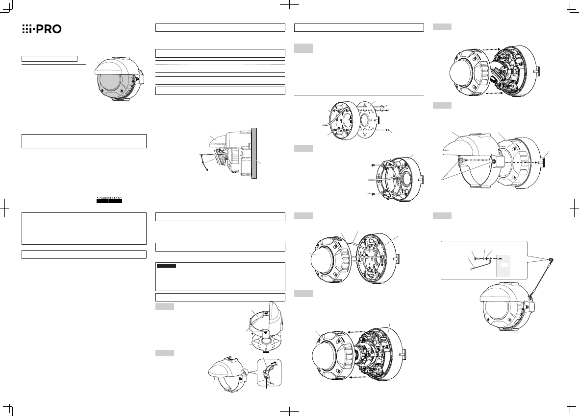
Step 1
Install the sunshade mount bracket and the base bracket on the
installation surface.
Prepare the fixing screw holes to fix the sunshade mount bracket (accessory) and the base bracket
(camera accessory or option) using template B provided with the camera or the option.
If necessary, prepare also a cable access hole using template B.
Fix the sunshade mount bracket and the base bracket using four fixing screws (M4: locally
procured) as shown in the illustration below.
Minimum pull-out strength: 196 N {44 lbf} (per 1 pc.)
Note:
When installing this product outdoors, be sure to apply waterproofing to the cable access hole
and the fixing screw holes.
Step 2
Fix the attachment plate on the base bracket.
Fix the attachment plate (camera accessory) on
the base bracket with four fixing screws for
attachment plate (M4x8 mm: camera accessory
or optional product accessory).
Recommended tightening torque:
0.78 N·m {0.58 lbf·ft}
Step 5
Adjust the camera.
After adjusting the angle of view, attach the enclosure to the camera as it was before.
Recommended tightening torque: 0.78 N·m {0.58 lbf·ft}
Step 6
Mount the sunshade.
Attach the sunshade to the upper side of the camera and fix it on the sunshade mount bracket
with the screws on the left and right of the sunshade using the bit (accessory).
Recommended tightening torque: 0.78 N·m {0.58 lbf·ft}
Spring washer (accessory)
Fixing screw
(M4: locally procured)
Washer (accessory)
Safety wire
(accessory)
Step 3
Connect the cables and mount the camera on the attachment plate.
When mounting the camera, be sure that the cable inlet is located at the upper side.
Step 4
Fix the camera.
Remove the enclosure from the camera and fix the camera firmly by tightening the camera fixing
screw (red).
Recommended tightening torque: 0.78 N·m {0.58 lbf·ft}
Sunshade
mount bracket
(accessory)
Sunshade
Camera
Step 7
Fix the safety wire.
Fix the safety wire attached to the sunshade to the foundation part of the construction or a part
where an adequate strength can be secured. Prepare a fixing screw (M4: locally procured)
according to the material of the surface where the safety wire is to be fixed.
Minimum pull-out strength: 196 N {44 lbf} (per 1 pc.)
Base bracket
(camera accessory
or option)
Sunshade mount bracket (accessory)
Fixing screws (4 pcs.)
(M4: locally procured)
Cable access hole
Fixing screw hole
(4 places)
Base bracket (camera accessory or option)
Fixing screw for attachment plate (4 pcs.)
(M4×8 mm {5/16 inches}: camera accessory
or optional product accessory)
Attachment plate
(camera accessory)
Cable
Cable inlet
Camera
Camera fixing screw (red)
Enclosure
Attachment plate
(camera accessory)
Screws on the left and
right of the sunshade
Ns0520-1042
Printed in China
© i-PRO Co., Ltd. 2022
For U.S. and Canada:
i-PRO Americas Inc.
For Europe and other countries:
i-PRO EMEA B.V.
https://www.i-pro.com/