User operation guide, Ir blaster ir receiver, Hardware installation – ABtUS MAX-HDMI408A-G User Manual
Page 3: Operation approach, Connection diagram
User Operation Guide
* Specifications are subject to changes without notice.
** For detail, updated Command Code and Application Software, please visit and download from www.abtussingapore.com
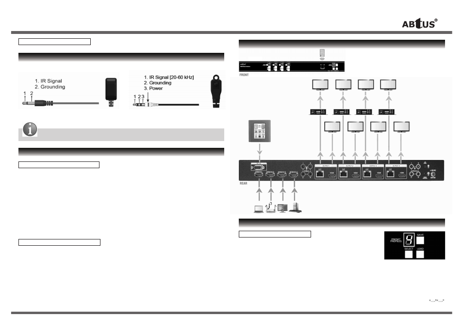
Definition of IR 3.5mm Jack
IR BLASTER
IR RECEIVER
Any IR extensions cables in the market that are compatible to the definition of the IR sockets for the matrix
can be used as replacement. However, do note that IR cables longer than 2m (6ft) may not work.
HARDWARE INSTALLATION
MAX-HDMI48A-G as Transmitter
1. Connect all sources to HDMI Inputs on the 4x4 HDMI over CAT-5 matrix master MAX-HDMI48A-G.
2. Connect each CAT-5 output port on the MAX-HDMI48A-G to respective CAT-5 input on the remote
receiver CAT-HDMI11RA-G.
3. Connect IR blaster to the MAX-HDMI408A-G and direct the IR blaster to point towards the built-in
IR receiver of the HDMI source devices.
4. Connect the +12V 5A DC power supply to the MAX-HDMI48A-G.
5. Power on all HDMI sources.
CAT-HDMI11RA-G as Receiver
1. Connect each HDMI output to HDMI displays.
2. Connect the CAT-5 input on the CAT-HDMI11RA-G to the CAT-5 output port on the
MAX-HDMI48A-G.
3. Connect IR receiver and place the IR receiver at the appropriate position that can receive the
IR signals sent from the users.
4. Dial the 8-level rotary control switch to adjust the HDMI signal level until the picture and sound are
clear. It is recommended to dial from weakest to strongest to find the optimal visual experience.
OPERATION APPROACH
Method A: Push-in Button
1. IN/OUT MAP
1) Use the “+”or “-” output push button to select the number of display
2) Use the “+”or “-” input push button to select the number of input source
“+”: change selected input/output port in ascending order
“-” : change selected input/output port in descending order
After you select the desired input/output port, the LED will blink twice and the setting will be effective
2. Save Mapping Mode
1) Keep pushing “output+ (save)” button until the output LED shows “d” to enter the Save Mapping Mode.
2) Use the “+”or “-” input push button to select the mapping configuration (1~8) which you want to save current
input/output mapping
3) After you select the desired mapping configuration number, the LED will blink twice & the mapping setting will be saved
4) If you push the “output- (preset)” button before the mapping setting is saved, the LED will show
to quit the Save Mapping Mode
IR
Remote
CONNECTION DIAGRAM
HDMI Out
HDMI Out
HDMI Out
HDMI Out
CA
T
-5 Out 1
HDMI Out
CA
T
-5 Out 2
HDMI Out
CA
T
-5 Out 3
HDMI Out
CA
T
-5 Out 4
HDMI Out
RS-232
HDMI IN 1
HDMI IN 2
HDMI IN 3
HDMI IN 4
ABtUS
CAT-HDMI11RA-G
(Receiver)
ABtUS
MAX-HDMI408A-G
User Operation Guide
* Specifications are subject to changes without notice.
** For detail, updated Command Code and Application Software, please visit and download from www.abtussingapore.com
Definition of IR 3.5mm Jack
IR BLASTER
IR RECEIVER
Any IR extensions cables in the market that are compatible to the definition of the IR sockets for the matrix
can be used as replacement. However, do note that IR cables longer than 2m (6ft) may not work.
HARDWARE INSTALLATION
MAX-HDMI408A-G as Transmitter
1. Connect all sources to HDMI Inputs on the 4x4 HDMI over CAT-5 matrix master MAX-HDMI408A-G.
2. Connect each CAT-5 output port on the MAX-HDMI408A-G to respective CAT-5 input on the remote
receiver CAT-HDMI11RA-G.
3. Connect IR blaster to the MAX-HDMI408A-G and direct the IR blaster to point towards the built-in
IR receiver of the HDMI source devices.
4. Connect the +12V 5A DC power supply to the MAX-HDMI408A-G.
5. Power on all HDMI sources.
CAT-HDMI11RA-G as Receiver
1. Connect each HDMI output to HDMI displays.
2. Connect the CAT-5 input on the CAT-HDMI11RA-G to the CAT-5 output port on the
MAX-HDMI408A-G.
3. Connect IR receiver and place the IR receiver at the appropriate position that can receive the
IR signals sent from the users.
4. Dial the 8-level rotary control switch to adjust the HDMI signal level until the picture and sound are
clear. It is recommended to dial from weakest to strongest to find the optimal visual experience.
OPERATION APPROACH
Method A: Push-in Button
1. IN/OUT MAP
1) Use the “+”or “-” output push button to select the number of display
2) Use the “+”or “-” input push button to select the number of input source
“+”: change selected input/output port in ascending order
“-” : change selected input/output port in descending order
After you select the desired input/output port, the LED will blink twice and the setting will be effective
2. Save Mapping Mode
1) Keep pushing “output+ (save)” button until the output LED shows “d” to enter the Save Mapping Mode.
2) Use the “+”or “-” input push button to select the mapping configuration (1~8) which you want to save current
input/output mapping
3) After you select the desired mapping configuration number, the LED will blink twice & the mapping setting will be saved
4) If you push the “output- (preset)” button before the mapping setting is saved, the LED will show
to quit the Save Mapping Mode
IR
Remote
CONNECTION DIAGRAM
HDMI Out
HDMI Out
HDMI Out
HDMI Out
CA
T
-5 Out 1
HDMI Out
CA
T
-5 Out 2
HDMI Out
CA
T
-5 Out 3
HDMI Out
CA
T
-5 Out 4
HDMI Out
RS-232
HDMI IN 1
HDMI IN 2
HDMI IN 3
HDMI IN 4
ABtUS
CAT-HDMI11RA-G
(Receiver)
ABtUS
MAX-HDMI48A-G