Block diagram (-sf and -qf), 4swm24 hardware manual – Applied Motion SWM24IP-3EE User Manual
Page 4
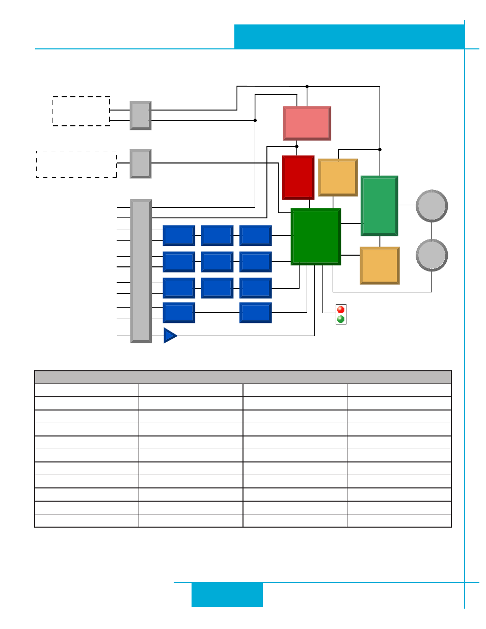
Block Diagram (-SF and -QF)
12-70 VDC
External
Power Supply
+
I/O 1+
Status
I/O 1-
I/O 2+
I/O 2-
I/O 3+
I/O 3-
I/O 4+
I/O 4-
AIN
GND
GND
+5VDC
+5V
RS-232
TX, RX, GND,+5V
-
Digital
Filter
Optical
Isolation
Software
Filter
Digital
Filter
Optical
Isolation
Software
Filter
Digital
Filter
Optical
Isolation
Software
Filter
Optical
Isolation
Software
Filter
I/O Connector
Power Conn
Comm Conn
motor
encoder
MOSFET
PWM
Power
Amplifier
5 Volt DC
Power Supply
3.3VDC
Logic
Supply
Voltage &
Temp
Monitor
DSP
Driver
Controller
Over-
Current
Monitor
I/O Functions (configure in software)
I/O 1
I/O 2
I/O 3
I/O 4
Step Input
Direction Input
Jog CW Input
Jog CCW Input
Limit CW Input
Limit CCW Input
Enable Input
Alarm Reset Input
Enable Input
Alarm Reset Input
Start/Stop Input
Change Speed Input
General Purpose Input
General Purpose Input
General Purpose Input
General Purpose Input
Brake Output
Brake Output
Brake Output
Brake Output
Fault Output
Fault Output
Fault Output
Fault Output
Motion Output
Motion Output
Motion Output
Motion Output
Tach Output
Tach Output
Tach Output
Tach Output
General Purpose Output General Purpose Output General Purpose Output General Purpose Output
4
SWM24 Hardware Manual
920-0068B
10/31/2013