Olson Technology ISX-3040 User Manual
Page 4
025-370494 REV X3
Page 4
INTRODUCTION
The Olson Technology Inc. IX40RPTX is a high quality, cost effective, Return Transmitter module designed around the latest
optical transmitter technology. It is designed to operate and meet full specifications with an optical output level of 1 to 3 mW. The
transmitter RF path includes a plug-in OMI pad which is preset at the factory for +7 dBmV carriers.
The IX40RPTX receives preconditioned +5 and -5 VDC from the Node and plugs directly into the preexisting locations within the
Node. The primary RF connection is made through the built in connector on the bottom of the transmitter. For models equipped
with a secondary laser, an SMB connector is located on the top of the transmitter. The transmitter can be ordered with an optical
connection that will match the factory setup. Heat transfer for the IX40RPTX is provided via the bottom surface of the module to
the Node housing for full outdoor temperature operation.
INSTALLATION / ENVIRONMENTAL CONSIDERATIONS
The IX40RPTX operates with an exterior temperature on the Node of -40 to + 60°C. However, like any other electronic device, it
will probably have a longer life span if it is not operated at the upper limit of it's temperature range continuously. Installation of
the IX40RPTX should be done such that water, dirt and other contaminates do not enter either the Node or the module. Do not
install equipment in locations that are accessible by either children or other unqualified personnel. This unit is meant to be field-
installed into the ISX-3040 Optical Node by qualified field service technicians.
To install the IX40RPTX, loosen the 6 closure bolts on the ISX-3040 Node casting enough free them from the other half of the
housing. Open the housing and locate the plug in module section of the Node. Place the IX40RPTX module into one of the 2
transmitter locations, making sure to orient the sub-D connector on the bottom of the IX40RPTX module in line with the mating
connector in the Node.
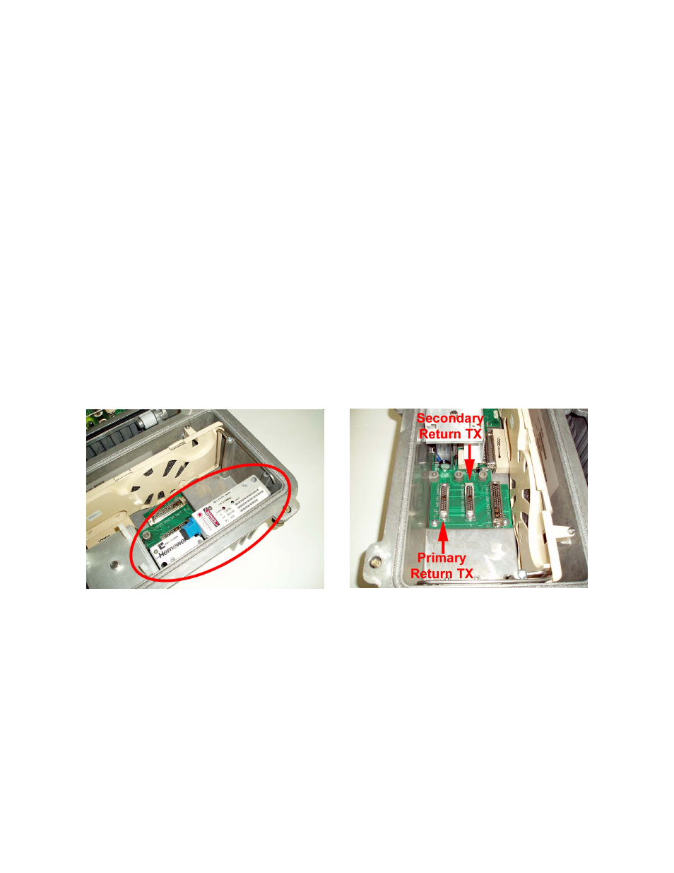
NOTE: If replacing an existing transmitter (fig 1), remove it and place the IX40RPTX in place of it.
Push the IX40RPTX into position firmly, seating the connector. Tighten the 2 captive screws firmly. Connect the incoming fiber to
the transmitter, then dress the fiber as to keep it clear of anything that may pinch or damage it.
NOTE: Be sure the fiber termination of the incoming fiber matches that of the transmitter, an easy way to tell is by the color of the
termination. The transmitter will have either a round green sticker (SC/APC), or a blue sticker (SC/UPC) on the fiber bulkhead. The
incoming fiber connector MUST match this color. If the sticker is green, but the fiber termination is blue (or vice versa), then the
signal passing through the fiber will be degraded and in many cases unusable.
Figure 1
Figure 2