RGBLink Driver 4 Quick Start User Manual
Quick start, View size the world, Driver 4
Driver 4–
Quick Start
Installation and cabling features
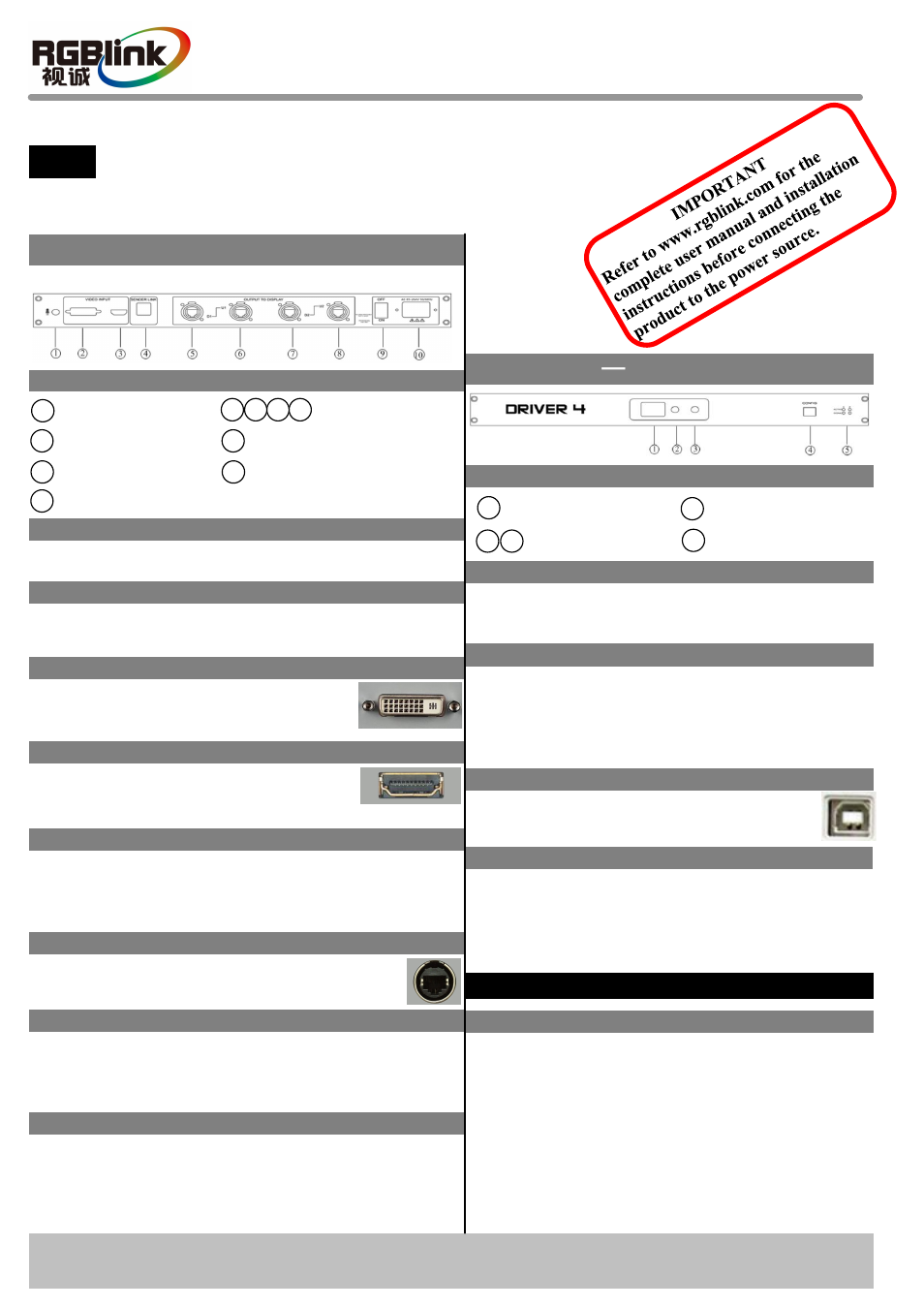
Rear Panel
Connections
Step 1-Mounting
Turn off or disconnect all equipment power sources.
Step 5-USB Interface
Driver 4 Quick Start
Rev 1.0
Page 1 of 2
Address: S603-604 Weiye Building Torch Hi-Tech Industrial Development Zone, Xiamen, Fujian Province, P.R.C
Tel: 00865925771197 Fax:00865925771202
Email: [email protected]
Step 4-HDMI Input
VIEW SIZE THE WORLD
NOTE
This guide provides quick start instructions for an experienced installer
to set up and operate the Driver 4.
For full installation, configuration, and operation details, please refer to
the Driver 4 user manual, which is available at
Step 3-DVI Input
Use to input DVI from DVI player or
computer with DVI connector.
Nixie Tube
Step 6-Gigabit Copper Port
Can receive video signal from HD player,
DVD and computer.
Local Control Front Panel Operation
Can control the brightness of LED sending card, and
the nixie tube will display the brightness value.
Use to cascade the device. Currently, Driver 4 can only
cascade 2 pieces, and only available for Colorlight Q7e
sending card.
Connect to LED screen through cable.
LED Indicator
Red: Power indicator, it lights when device has power
supply.
Green: Signal indicator, it lights when device has
signal input.
USB Control Port of Sending Card
User can connect PC via USB cable and
control sending card software.
Function Button
Function Button
Button 2: Down key, can switch to the top level
brightness value.
Button 3: Up key, can switch to the next level
brightness value.
How to connect
Connect the HD player, DVD or computer to the
HDMI input interface with HDMI cable.
Connect the DVI player or computer with DVI
interface to the DVI interface with DVI cable.
Connect the computer to the USB control port of
sending card with USB cable.
Connect the receiving card of LED Display to the
Gigabit Copper Port with cable.
1
2
DVI Input Interface
Audio Input Interface
Switch
5
9
8
Gigabit Copper Port
3
HDMI Input Interface
Power
7
6
USB Interface
4
10
Step 2-Audio Input
Connect to microphone or the device with audio
interface.
Step 7-Power
Plug in power cord which has IEC connector, Driver 4
supports AC power from 85 to 264V, 50-60Hz, which
means world wide compatible.
Power On
Connect one end of the power with the device, the other
end into a socket, and push power switch to ON
position. Red power indicator light means the device
works normally.
1
4
USB control Port of
Sending Card
Nixie Tube
5
2
Function Button
LED Indicator
3
Operation Manual