Module wiring & connections, Dual digital wiring when used with the vcm-x e-bus, Vcm-x component & systems wiring – Orion System VCM-X E-BUS Component User Manual
Page 101
VCM-X Component & Systems Wiring
Module Wiring & Connections
101
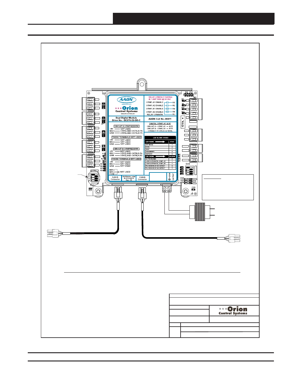
Dual Digital Wiring When Used With The VCM-X E-BUS
FILENAME
DATE:
S. Olson
DESCRIPTION:
PAGE
DRAWN BY:
When Used With Orion VCM-X E-BUS Controller
JOB NAME
06/05/15
DualDigital-1A.CDR
Dual Digital Module Wiring
1
Wiring For Dual Digital Module When Used With Orion VCM-X E-BUS Controller
Connect To Other
WattMaster-Approved
E-BUS Expansion Module(s)
HSSC Cable
HSSC Cable
Connect To VCM-X E-BUS
OE370-23-DD-C
Dual Digital Module
+5V
SIG 2
GND
OPTI
O
N
S
ALARM
ANALOG
STAT
+5V
COMM
GND
SIG 4
GND
BIN 2
R1
R2
GND
RELAYS
ADDRESS
SIG 3
+5V
GND
BIN 1
COM
+5V
SIG 1
R3
R4
Rc
AO1
AO2
PWM1-
PWM1+
PWM2-
PWM2+
PWR
24 VAC Transformer
24 V
A
C
GND
WARNING!!
Observe Polarity! All boards must
be wired with GND-to-GND and 24
VAC-to-24 VAC. Failure to observe
polarity could result in damage to
the boards.
Software
versions 1.04 or
above allow two
modules per
HVAC unit. If
using two
modules, set the
1st to address 1
and the 2nd to
address 2.
Figure 77: OE370-23-DD-A Dual Digital Module to VCM-X E-BUS Controller Wiring