ShoreLand'r PS8X17TB User Manual
Page 10
Midwest Industries, Inc.
Ida Grove, IA 51445
800.859.3028
www.shorelandr.com
0004005
Page 10
Rev D 08/08/2011
Place the battery inside the battery box. Route the section of the wire
harness over to the battery and connect it to the battery using the con-
nector spades of the wire harness. Connect the Red wire to the positive
terminal and the white wire to the negative terminal. The battery will
maintain its charge when it is connected to the tow vehicle and is used
only in the event the trailer becomes disconnected from the tow vehicle.
In the event it does become disconnected the pin will be removed from
the breakaway switch allowing the battery to power the brakes causing
them to stop and trailer and hold it in position for up to twenty minutes
after disconnect.
TIRE & WHEEL ASSEMBLY
Mount the tire and wheel assemblies using the 1/2” fine threaded tapered
lug nuts provided. Tighten to 85-95 ft./lb. torque using the rotation pat-
tern as shown in the ShoreLandr’s Owners Manual.
Re-torque the lug nuts after 50 miles driving and then periodically
thereafter.
Front Ramp Kit
The front ramp kit is designed to attach to the front cross frame tube
of the PS5x10, PS5x14, and the PS8x17 series. The kit includes
the ramps and all attaching hardware for converting the ramps into
a front shield while being stored for transport. The ramp retainer
channels are designed to accommodate U-bolts for attaching them
to either a 2x3” or 2x4” frame tube.
Installing the ramps in the following manner will allow for the re-
moval of the ramp from the
*left side of the trailer first.
*Left and Right side of trailer is indicated by standing at the
rear of the trailer.
Installation Instructions
•
Locate the four ramp retainer attachment channels. Note that
they are all identical.
•
The two ramp retainer attachment channels on the
*right side
of the trailer will be installed on the front side of the trailer front
frame tube so it will support the ramp as shown.
•
Note that the kit is supplied with two different size U-bolts. Se-
lect the proper size to fit your frame tube. Place one of the
correct size square U-bolt around the front frame tube so the
legs of the U-bolt are pointing forward. Align the holes in one of
the ramp retainer attachment channels with the U-bolt legs, then
slide into position. Note that this channel is mounted on the
front side of the frame tube. Secure in place with 3/8” lock
washers and 3/8” hex nuts.
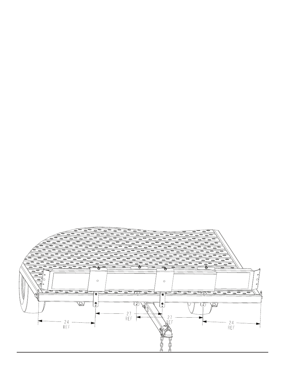
•
Position the U-bolt so it is 24” from the outside of the side
frame tube.
•
Repeat the mounting process on the second channel. Position
this ramp retainer attachment channel so that the center hole
in the ramp retainer bracket is 27” from the center hole in the
ramp retainer channel just installed. Tighten enough to hold in
position until the ramp is installed for final spacing.
•
Install the remaining two ramp retainer attachment channels
on the left side of the trailer to the rear side of the front frame
tube using the steps above. Placing them on the rear of the
frame tube allows the ramps to overlap past each other in the
middle.
•
Once all four of the ramp retainer attachment channels are at-
tached to the frame, position the right ramp into the ramp re-
tainer attachment channels. The ramp can either be slid into
the end of the channels or else placed in the approximate posi-
tion, then rotated into place.