AXING SKM 1-03 User Manual
Page 5
Operation Instructions SKM 1-03/-04/-05/-06 and 2-03/-04
Chapterl 1: Common
2014-09-17
© AXING AG | Switzerland | Reserving change in design and type - We cannot be held liable for printing errors
5
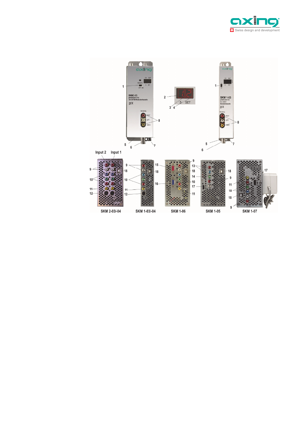
1.2.1
Display elements and connections
1. Control switch to program channel in ON position.
The switch must be set to OFF position when programming is ready!
2. Channel number (CCIR)
3. S channel indicator LED
4. Programming mode indicator LED
5. RF output and DC input (for installation in basic unit SKS x-x)
6. DC input (only for standalone installation)
7. Grounding screw
8. Video/Audio connectors for monitoring (cinch)
9. Audio inputs (cinch)
10. YPbPr/RGB inputs (cinch)
11. FBAS video input (cinch)
12. S-Video input (hosiden)
13. YPbPr inputs (Cinch)
14. Y or FBAS-Video input
15. VGA input
16. VGA output
17. HDMI input
18. USB input for software update
Fig. 2: Display elements and
connections