Connection diagram, Device, Dvi-d input – Datapath x4 User Manual
Page 11
The main control dialog is divided into the following groups:
DVI-D Input
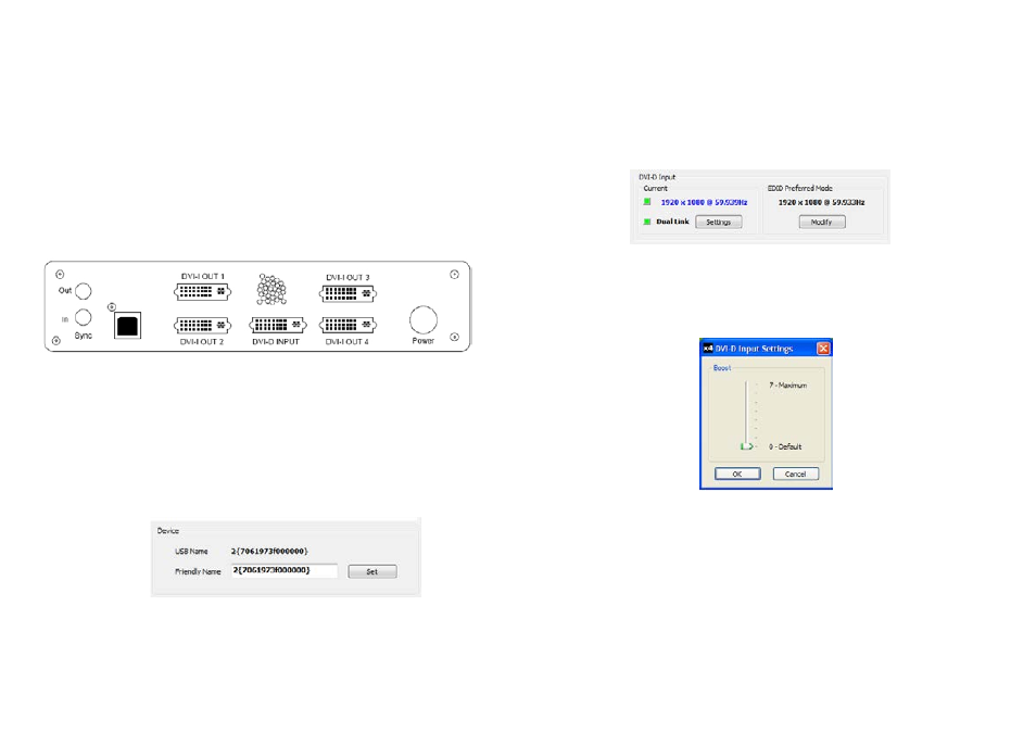
Connection Diagram
The connection diagram displays a schematic view of the rear panel of the x4 to assist in identifying
the connectors.
Fig.5
Device
The unique USB device name that is connected is displayed in the Device group. It is possible to asso-
ciate a more user friendly name such as “First Four Outputs”. The friendly name is stored in non-vola-
tile storage on the x4 and can to help identify the device during future configurations. Specific devices
connected to your PC can be selected using the Select Device.. command on the File Menu. The x4s
will be listed by the USB Device or by a previously configured friendly name.
Fig.6
18
DVI-D Input
The DVI-D Input group displays the current DVI mode that is being captured (if any) and the preferred
mode that has been programmed into the x4’s EDID. Use the Modify button to update the EDID. The
small square to the left of the current input resolution indicates whether the x4 has frame-locked to the
input source.
• Green – The outputs are frame-locked to the input dot clock and vertical sync
• Grey – The outputs are not frame-locked
To change the timings of the input EDID click on the Modify button and the following dialog is
displayed. Fig 9.
19
To boost the equalization hardware click on the Settings button and the following dialog is displayed.
Fig 8.
Fig.8
Use the slider to compensate for the loss signal quality due to DVI cable lengths over 5 m. The equaliza-
tion hardware can compensate for cables up to 20m in length.
Fig.7