Description – Datapath x4 User Manual
Page 7
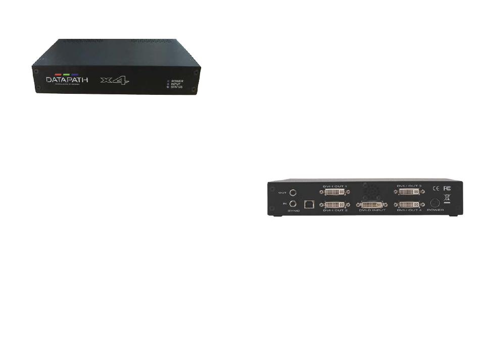
Rear Panel
Fig.2
Sync Sockets (Not x4-1U)
The Sync sockets are provided for future genlock enhancements. They should be left unconnected.
USB Socket
The USB socket is used to connect the x4 to a PC via a USB connection using the supplied USB Type A to
Type B cable. Configuration of the x4 is programmable via an application utility allowing easy control of
cropping, scaling, rotation and gaps.
11
Description
Front panel
Fig.1
Operation Indicators
The front panel has three LEDs to indicate the operational status of the x4:
• Power
• Input
• Status
Power
• When illuminated, the Power LED indicates the x4 is connected to a mains supply using the
supplied PSU.
Input
• When illuminated, the Input LED indicates a valid DVI source is connected.
Status
• Continuous illumination – Indicates the x4 is operating normally.
• Flashing – Unit is operating over the normal operating temperature. Ensure the input fan vent is not
blocked.
• If the Status LED goes off and remains off this indicates that the settings configured in the x4
application no longer match the input, this is normally the result of a change of input. The x4 will
compensate for the settings and reconfigure itself to display as near to the settings as possible. The
output will still be displayed but not necessarily as expected.
When the x4 device is connected to a PC by a USB cable and the x4 Control application is active, then all
three lights flash in turn to help to identify which unit is being controlled.
10
Output Framelock (x4-1U only)
The Output Framelock is intended to ease the setup of the x4-1u by setting all four outputs to the exact
same timings by replicating the the timings of the first output.
Push and hold the button for approx 3 seconds to activate the Output Framelock. (The three LEDs will
flash to indicate the operation is successful).
If the first output is set to “Use The Monitor’s Preferred Mode”, the EDID timings will be sampled from the
monitor, and written into the x4 defaults. Output 1 will then be set to “Always Use the Default Mode”.
If output 1 is set to “Always Use the Default Mode”, no action is taken on this channel.
Output 2,3 and 4 will have their timing defaults overwritten with those from Output 1 and they will also be
set to “Always Use the Default Mode”.
The onboard micro in the x4 will then enable the framelocking.
The x4 will now ignore the output monitor connections until it is changed using the x4 application.