Powermax – Hypertherm Powermax105 Service Manual User Manual
Page 265

Power SuPPly ComPonent rePlaCement
powermax
105 Service Manual
9-67
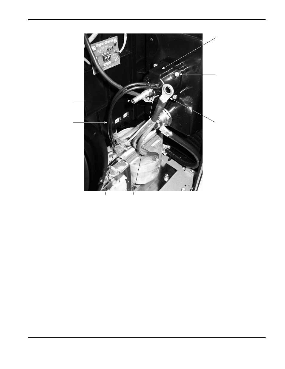
8. Remove the brass fitting by pushing it out through the front of the quick disconnect receptacle housing.
9. Remove the quick disconnect receptacle by removing the four mounting screws that secure the quick disconnect
receptacle to the front end panel.
10. Secure the new quick disconnect receptacle to the front end panel by tightening the four supplied mounting screws
to 23 kg cm (20 in.-lbs).
11. Insert the small end of the new brass fitting, from the front of the power supply, into the center hole of the quick
disconnect receptacle until fully seated.
12. Install the plastic washer over the brass fitting and the plastic hub on the rear of the quick disconnect receptacle.
13. Place the ring terminal over the brass fitting and tighten the new brass nut onto the brass fitting. Tighten the nut to
46.1 kg cm (40 in.-lbs).
14. Push the 90° push-to-connect fitting onto the brass fitting until fully seated.
15. Route the nozzle wires through the protective sheathing in the center panel.
16. Route the torch interface cable through the upper grommet.
Brass fitting
Ring terminal
Quick disconnect
receptacle
Mounting screws (4)
Nozzle wires (2)
Plastic hub
Protective
sheathing