6 - analog signals, Introduction, Analog signals – Measurement Computing ZonicBook 618E rev.3.4 User Manual
Page 49
Analog Signals
6
Introduction …. 6-1
Analog Common …… 6-3
Current Source (ICP) with Transducer Fault Detection ……. 6-3
Input Coupling …… 6-3
Programmable Gain Amplifier (PGA) …… 6-3
Low-Pass Anti-Aliasing Filter …… 6-4
Overrange Detection …… 6-4
Simultaneous Sample and Hold (SSH) …… 6-7
Transducer Electronic Data Sheet (TEDS) Support …… 6-7
Source Output (Excitation Source) …… 6-8
LEDs …… 6-10
Analog Triggers …… 6-11
Using Accelerometers …… 6-13
Introduction
ZonicBook/618E includes circuitry for dynamic analog signal conditioning. The circuitry provides a way
for the ZonicBook to interface with piezoelectric transducers that include, but are not limited to:
accelerometers, microphones, tachometers, and force/pressure transducers.
The analog input signal lines, which connect to the dynamic signal conditioning circuit, do so via the
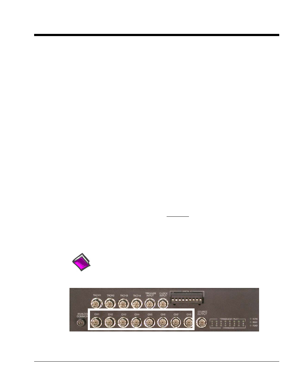
BNCs labeled CH1 through CH8. These are located on the bottom row of ZonicBook/618E’s front panel.
The center conductor of each BNC is the signal HI (High) and the BNC shell is the signal LO. The BNC
shell is common to all eight input channels and is not isolated from earth ground. (See the following
section, Analog Common). The Source Output BNC [for Excitation] is discussed later in this section.
Depending on your application, you will need to set several software parameters. Proper settings will
allow the software to organize data to meet your requirements.
Reference Note:
For detailed information, refer to the applicable software document, e.g., eZ-TOMAS,
eZ-Analyst, or eZ-NDT. PDF versions of the document can be accessed from the data
acquisition CD via the <View PDFs> button on the CD’s opening screen.
ZonicBook/618E, Front Panel
The white rectangle borders the BNC connectors for analog signal input channels 1 through 8.
ZonicBook/618E
878595
Analog Signals 6-1