Hardware setupconfiguration, Caution – Measurement Computing WaveBook rev.3.0 User Manual
Page 35
WaveBook User’s Manual,
ch03A 6-18-99
WBK Expansion Options 3-3
Hardware SetupConfiguration
Unit
Channel #
WaveBook
0 (dig I/O)
WaveBook
1-8
1
st
WBK10
9-16
2
nd
WBK10
17-24
3
rd
WBK10
25-32
4
th
WBK10
33-40
5
th
WBK10
41-48
6
th
WBK10
49-56
7
th
WBK10
57-64
The analog input channel numbers are determined by the order of connection
among the WaveBook and attached WBK10/10H units.
• Channel 0 is the WaveBook’s 8-bit digital I/O port.
• Channels 1 through 8 are the WaveBook’s main channels.
• Channels 9 through 16 are located on the first expansion unit connected
directly to the WaveBook.
• Additional channel numbers (in groups of 8) are added consecutively with
added WBK10/10Hs (see table).
8
th
WBK10
65-72
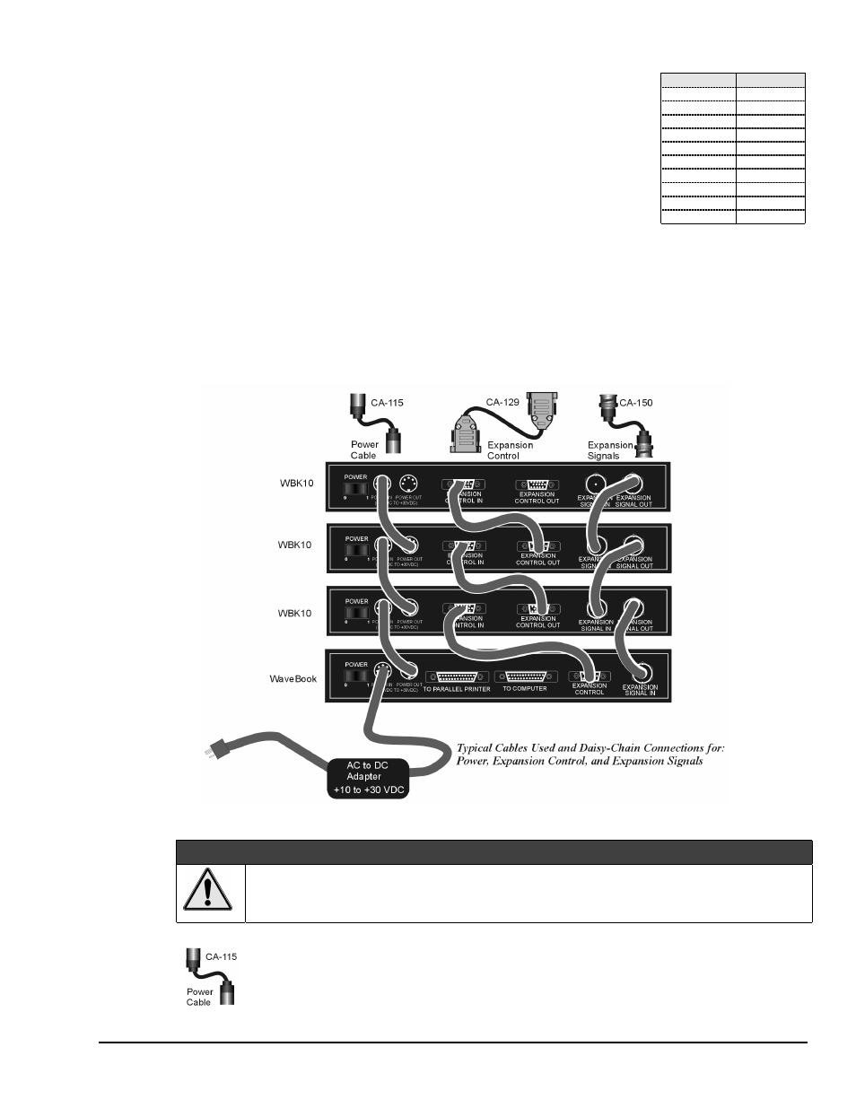
Power, Expansion Control, and Expansion Signal Connections
WBK expansion modules can be configured in various ways, such as:
• A WBK10/10H connects to a WaveBook or to another WBK10/10H.
• A lone WBK10/10H in the system connects directly to the WaveBook.
• An add-on WBK10/10H connects to the previous WBK10/10H in a daisy-chain fashion.
• Other WBK expansion modules are connected in a similar way.
You must make connections for power, expansion control, and expansion signals. A system using three
WBK10 modules (daisy-chained to a WaveBook) is depicted in the following figure.
Example of WaveBook and WBK10 Daisy-Chain
s
CAUTION
CAUTION
CAUTION
CAUTION
Do not daisy-chain the power connections of more than three WBK10/10H units.
Daisy-chaining a power connection to a fourth module will exceed the power connector
5 amp current limit.
CA-115 Power Cables. CA-115 cables are 6 inches long and have two 5-pin male DIN connectors.
CA-115s are frequently used to link WaveBook’s power out to a WBK10/10H module’s power in
connector. CA-115 cables are also commonly used to link WBK10/10H power out connectors to
the next daisy-chained module’s power in. See previous figure.