Sundance SMT370v2 User Manual
Page 10
Version 2.0
Page 10 of 46
SMT370v2/v3 User Manual
Ressource occupied.
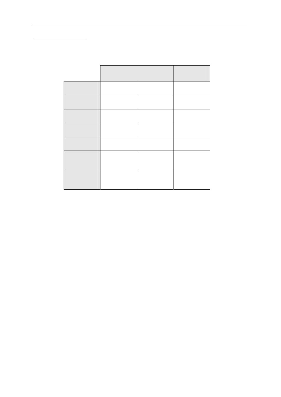
The default firmware, as it comes with the board, uses FPGA resources, such as
Ram Blocks, Flip-flop, Slices, I/O pads. The following table gathers all of them:
Number
used
Out of
Percentage
of utilisation
Number of
External IOBs
247
324
76%
Number of
RAMB16s
9
40
22%
Number of
SLICEs
1059
5120
20%
Number of
BUFGMUXs
6
16
37%
Number of
DCMs
2
8
25%
Number of
External
DIFFMs
1
162
1%
Number of
External
DIFFSs
1
162
1%
Figure 2 - FPGA utilisation.
Most of the resources are not used by the default firmware, which allows the user to
implement some extra processing such as for example digital filters to add some
processing gain to the chain.
Memory.
The SMT370 is populated with 32Mbits of ZBTRAM (32 bits x 1Meg). It is connected
to the FPGA, which controls read and write operations. The default FPGA bit stream
implements a pattern generator which consists in storing a pattern into the memory,
reading it back continuously and sending data out to the DAC. This generator is
controlled via bits in the control registers. It can be loaded, started and stopped by
setting bits. For more details, see further in the documentation, the part dealing with
control registers.
This pattern generator feature is also called Arbitrary Waveform Generator (AWG).
Please, note that to change of waveform, the memory has to be reloaded and the
pattern generator to be re-started. This is due to the default firmware starting reading
data from address 0, i.e. the start address is not a parameter, unlike the size is.