Other common controls and displays, Digital trim and pan, Phase switch – Teac DM-24 User Manual
Page 51: Assignable inserts, Input/return assignments, Meter, Eq and buss assignments, Fader section, Mute and fader groups, Digital trim control
7 – Module operations—Common area indicators and controls
TASCAM DM-24 Reference Manual
51
Other common controls and displays
Digital trim and pan
There are also two other
controls visible at the bottom of the screen—the digi-
tal trim and pan—above the soft key labels. These are
dealt with below (“Digital trim control” on page 51
and “Pan control” on page 51.
Phase switch
This on-screen switch reverses the
phase of the input signal (use the
ENTER
key to tog-
gle on and off).
In the case of linked pairs, each channel’s phase is
independently reversible.
Assignable inserts
If one of the assignable sends
and returns has been assigned to this channel (two
send/return pairs in the case of a linked pair), the
insert can be turned on or off.
The status of the insert (pre- or post) is shown by the
small “cutout” on the left of the on-screen button.
Input/return assignments
The current assign-
ments for this module, depending on whether it is
being used as an input or return module, are shown.
They cannot be changed from this screen. Use the
fourth module (
SETUP
) screen (“Setup screen” on
page 57) or the dedicated I/O setup to change these
settings (“Setting up the I/O” on page 36).
Meter
The on-screen meter gives a reading taken
from the defined metering point, which is switchable
here between the input, pre-fader and post-fader.
EQ and buss assignments
These buss assign-
ments, together with the status of the EQ (on or off)
are shown at the right of the screen.
In addition, the EQ response curve is shown at the
top of the screen. If the EQ is disabled, this is
“grayed out”, and is solid if the EQ is enabled.
NOTE
It is not possible to change the buss assignments or the
EQ switching from here. Use the dedicated keys (to the
left of the display screen) for this. Full details are in
“Channel-to-buss assignments by channel” on page 41.
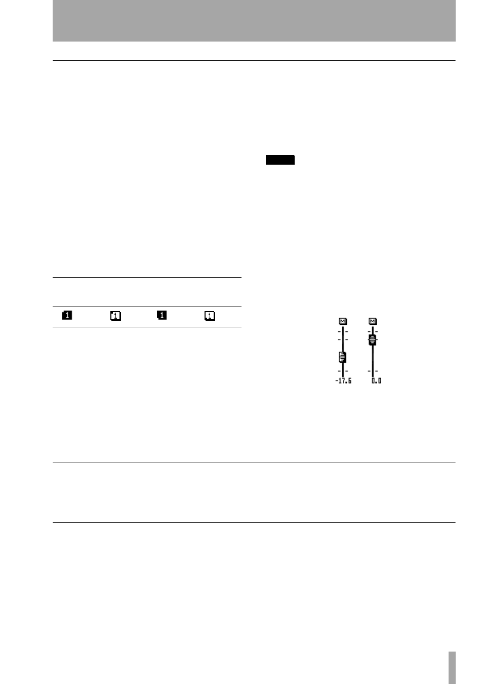
Fader section
The current fader position (which
will almost always correspond to the physical fader
position, except when automation motor control is
turned off) as well as the mute status, is provided on-
screen, as is the mute status of the module.
The exact numerical value of the level is also dis-
played here. This allows the fader to be “normalized”
easily, as when the fader is at the zero position, the
on-screen fader knob is reversed.
Mute and fader groups
Any assignments to
mute and fader groups are shown to the right of the
screen.
These cannot be changed here (see “Grouping” on
page 69 for full details).
Digital trim control
The digital trim control (POD 1 of the bottom row)
allows the adjustment of the module level between
–50dB
and
+10dB
in 61 0.5dB steps.
See also “Global digital trim” on page 59.
Pan control
The pan control is on the bottom row of the PODs
(that is, move the cursor to the bottom row and use
the PODs).
The pan control is controlled by POD 4. Hard left is
represented by
L
, and hard right by
R
. The center
position is represented by
C
, and there are 201 possi-
ble pan positions available.
To center the pan position easily, move the cursor to
the
CENTER
on-screen button, and press
ENTER
.
If the channel is odd-numbered and is not part of a
stereo linked pair, it can be ganged to the module to
the right (even-numbered channels can be linked to
odd-numbered channels to the left). If this
GANG
con-
trol is enabled (move the cursor to it and press
Pre-fader
Post-fader
On
Off
On
Off