Connecting the ac power cord – H3C Technologies H3C S5500 Series Switches User Manual
Page 46
38
Table 27 Power cord connection methods of the S5500-EI Switch Series
Switch module
Power supply mode
Connection method
S5500-28C-EI
S5500-52C-EI
AC power supply
RPS power supply
Connect RPS power cords of
S5500-28C-EI, S5500-52C-EI and
S5500-28C-PWR-EI
S5500-52C-PWR -EI
AC power supply
RPS power supply
Connecting the RPS power cord of the
S5500-28C-PWR-EI and
S5500-28C-EI-DC
-48V DC power supply
Connecting the –48 VDC power cord
RPS power supply
Connect RPS power cords of
S5500-28C-EI, S5500-52C-EI and
S5500-28F-EI
PSR150-A/PSR150-A1: AC power
supply
PSR150-D/PSR150-D1: -48V DC
power supply
Connecting the –48 VDC power cord
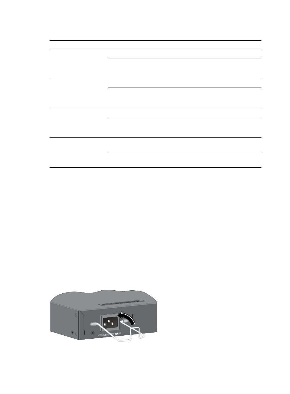
Connecting the AC power cord
1.
Wear an ESD-preventive wrist strap, and make sure it makes good skin contact and is well
grounded.
2.
Install the bail latch to prevent the AC power cord from accidentally falling off. Attach the bail latch
into the holes located at the two sides of the AC power receptacle. Then pull the bail latch upwards
(see in
).
3.
Connect one end of the AC power cord to the AC receptacle on the switch (see callout 1 in
,
4.
Pull the bail latch down to secure the plug to the AC receptacle (see callout 2 in
).
5.
Connect the other end of the AC power cord to the AC power source.
6.
Verify that the system status LED (PWR/SYS) on the front panel of the switch is ON. If the LED is ON,
it shows the power cord is correctly connected.
Figure 32 Connecting an AC power cord to a horizontal AC power socket (1)
- H3C S12500X-AF Series Switches
- H3C S12500X-AF Series Switches
- H3C S12500X-AF Series Switches
- H3C S12500 Series Switches
- H3C MSV 50
- H3C S12500 Series Switches
- H3C S9500E Series Switches
- H3C S7500E Series Switches
- H3C WA2200 Series WLAN Access Points
- H3C S12500-X Series Switches
- H3C SR6600
- H3C S9500E Series Switches
- H3C WA3600 Series Access Points
- H3C WA3600 Series Access Points
- H3C S9500E Series Switches
- H3C MSR 900
- H3C S12500 Series Switches
- H3C S12500 Series Switches
- H3C MSR 900
- H3C MSR 900
- H3C MSR 900
- H3C MSR 900
- H3C S9500E Series Switches
- H3C WA3600 Series Access Points
- H3C S9500E Series Switches
- H3C S12500 Series Switches
- H3C LSBM1WCM2A0 Access Controller Module
- H3C S6800 Series Switches
- H3C LSBM1WCM2A0 Access Controller Module
- H3C S10500 Series Switches
- H3C LSBM1WCM2A0 Access Controller Module
- H3C S10500 Series Switches
- H3C LSBM1WCM2A0 Access Controller Module
- H3C WA3600 Series Access Points
- H3C S6300 Series Switches
- H3C LSBM1WCM2A0 Access Controller Module
- H3C S6800 Series Switches
- H3C S6300 Series Switches
- H3C S6300 Series Switches
- H3C MSR 900
- H3C SR6600
- H3C MSR 900
- H3C LSBM1WCM2A0 Access Controller Module
- H3C LSBM1WCM2A0 Access Controller Module
- H3C WA3600 Series Access Points
- H3C WA3600 Series Access Points
- H3C WA3600 Series Access Points
- H3C S10500 Series Switches
- H3C S10500 Series Switches
- H3C S10500 Series Switches
- H3C S10500 Series Switches
- H3C S10500 Series Switches
- H3C S10500 Series Switches
- H3C S10500 Series Switches
- H3C S10500 Series Switches
- H3C S10500 Series Switches
- H3C S7500E Series Switches
- H3C S7500E Series Switches
- H3C S6300 Series Switches
- H3C S6300 Series Switches
- H3C S6300 Series Switches
- H3C S6300 Series Switches
- H3C S10500 Series Switches
- H3C S6300 Series Switches
- H3C S5820X Series Switches
- H3C S10500 Series Switches
- H3C WX3000E Series Wireless Switches
- H3C WX3000E Series Wireless Switches
- H3C S5820X Series Switches
- H3C S12500-X Series Switches
- H3C S12500-X Series Switches
- H3C S7500E Series Switches
- H3C S10500 Series Switches
- H3C S7500E Series Switches
- H3C S7500E Series Switches
- H3C S7500E Series Switches
- H3C S7500E Series Switches
- H3C WX3000E Series Wireless Switches
- H3C WX3000E Series Wireless Switches
- H3C WX3000E Series Wireless Switches
- H3C S6300 Series Switches
- H3C S6300 Series Switches
- H3C S6300 Series Switches
- H3C S9500E Series Switches
- OAA For Routers
- H3C S7500E Series Switches
- H3C WA2200 Series WLAN Access Points
- H3C S5120 Series Switches
- H3C S7500E Series Switches
- H3C WA2200 Series WLAN Access Points
- H3C S7500E Series Switches
- H3C WA2200 Series WLAN Access Points
- H3C WA2200 Series WLAN Access Points
- H3C WA2200 Series WLAN Access Points
- H3C WA2200 Series WLAN Access Points
- H3C S7500E Series Switches
- H3C S5120 Series Switches
- H3C S5800 Series Switches
- H3C S7500E Series Switches
- H3C WA2200 Series WLAN Access Points
- H3C WA2200 Series WLAN Access Points
- H3C S6800 Series Switches
- H3C S5820X Series Switches
- H3C S5820X Series Switches
- H3C S5120 Series Switches
- H3C S3100V2 Series Switches
- H3C S5820X Series Switches
- H3C S5830V2 Series Switches
- H3C S3100V2 Series Switches
- H3C S5830 Series Switches
- H3C S5800 Series Switches
- H3C S3100 Series Switches
- H3C S5820X Series Switches
- H3C S5120 Series Switches
- H3C S5800 Series Switches
- H3C S5120 Series Switches
- H3C S6800 Series Switches
- H3C S6800 Series Switches
- H3C S5820X Series Switches
- H3C S5820X Series Switches
- H3C S6800 Series Switches
- H3C S6300 Series Switches
- H3C LSBM1WCM2A0 Access Controller Module
- H3C LSBM1WCM2A0 Access Controller Module
- H3C LSBM1WCM2A0 Access Controller Module
- H3C LSBM1WCM2A0 Access Controller Module
- H3C S6300 Series Switches
- H3C LSBM1WCM2A0 Access Controller Module
- H3C S5130 Series Switches
- H3C S6300 Series Switches
- H3C S5130 Series Switches
- H3C S5820V2 Series Switches
- H3C S5130 Series Switches
- H3C S6300 Series Switches
- H3C S5830V2 Series Switches
- H3C S6300 Series Switches
- H3C S5130 Series Switches
- H3C S5130 Series Switches
- H3C S6300 Series Switches
- H3C S6300 Series Switches
- H3C S6300 Series Switches
- H3C S6300 Series Switches
- H3C S5130 Series Switches
- H3C S5130 Series Switches
- H3C S5130 Series Switches
- H3C S5130 Series Switches
- H3C S5830 Series Switches
- H3C S5830 Series Switches
- H3C S5830 Series Switches
- H3C S6300 Series Switches
- H3C S6300 Series Switches
- H3C S5830V2 Series Switches
- H3C S5830V2 Series Switches
- H3C S5130 Series Switches
- H3C S5130 Series Switches
- H3C LSBM1WCM2A0 Access Controller Module
- H3C LSBM1WCM2A0 Access Controller Module
- H3C LSBM1WCM2A0 Access Controller Module
- H3C S9800 Series Switches
- H3C S9800 Series Switches
- H3C LSBM1WCM2A0 Access Controller Module
- H3C LSBM1WCM2A0 Access Controller Module
- H3C S5560 Series Switches
- H3C S5560 Series Switches
- H3C S5560 Series Switches
- H3C S5560 Series Switches
- H3C S5560 Series Switches
- H3C S9800 Series Switches
- H3C S5500 Series Switches
- H3C S5500 Series Switches
- H3C S5500 Series Switches
- H3C LSBM1WCM2A0 Access Controller Module
- H3C S9800 Series Switches
- H3C S5130 Series Switches
- H3C S5130 Series Switches
- H3C S5500 Series Switches
- H3C S5120 Series Switches
- H3C S5120 Series Switches
- H3C S5120 Series Switches
- H3C S5120 Series Switches
- H3C S5120 Series Switches
- H3C S3100 Series Switches
- H3C S3100 Series Switches
- H3C S3600V2 Series Switches
- H3C S3100V2 Series Switches
- H3C S3100V2 Series Switches
- H3C S3100 Series Switches
- H3C S3100 Series Switches
- H3C S6800 Series Switches
- H3C S6800 Series Switches
- H3C S6800 Series Switches
- H3C S6800 Series Switches
- H3C S6800 Series Switches
- H3C S6800 Series Switches
- H3C S3100V2 Series Switches
- H3C S3100V2 Series Switches
- H3C MSR 900
- H3C LSBM1WCM2A0 Access Controller Module
- H3C MSR 900
- H3C MSR 3600
- H3C MSR 900
- H3C MSR 3600
- H3C MSR 3600
- H3C MSR 3600
- H3C MSR 3600
- H3C MSR 3600
- OAA For Routers
- OAA For Routers
- H3C MSR 900
- H3C MSR 900
- H3C MSR 900
- H3C MSR 20-1X
- H3C MSR 900
- H3C MSR 30
- H3C MSR 900
- H3C S12500-X Series Switches
- H3C S12500-X Series Switches
- H3C S12500-X Series Switches
- H3C S12500-X Series Switches
- H3C S12500-X Series Switches
- H3C S12500-X Series Switches
- H3C S9800 Series Switches
- H3C S9800 Series Switches
- H3C S12500-X Series Switches
- H3C S9800 Series Switches
- H3C S9800 Series Switches
- H3C S9800 Series Switches
- H3C S9800 Series Switches
- H3C S9800 Series Switches
- H3C S9800 Series Switches
- H3C S9800 Series Switches
- H3C S6800 Series Switches
- H3C S6800 Series Switches
- H3C S6800 Series Switches
- H3C S6800 Series Switches
- H3C S6800 Series Switches
- H3C S6800 Series Switches
- H3C S6800 Series Switches
- H3C S6800 Series Switches
- H3C S6300 Series Switches
- H3C S5130 Series Switches
- H3C SR8800
- H3C LSBM1WCM2A0 Access Controller Module
- H3C SR6600
- H3C SR6600
- H3C SR8800
- H3C SR6600
- H3C LSBM1WCM2A0 Access Controller Module
- H3C SR6600-X
- H3C SR6600-X
- H3C SR6600-X
- H3C SR6600
- H3C SR6600
- H3C SR6600
- H3C SR6600
- H3C SR6600
- H3C MSR 50
- H3C MSR 50
- H3C MSR 2600
- H3C MSR 2600
- H3C MSR 20-2X[40]
- H3C MSR 900
- H3C MSR 900
- H3C MSR 800
- H3C MSR 800
- H3C MSR 800
- H3C WX3500E Series Access Controllers
- H3C WX3000 Series Unified Switches
- H3C WA3600 Series Access Points
- H3C WA3600 Series Access Points
- H3C WA3600 Series Access Points
- H3C WA3600 Series Access Points
- H3C WA3600 Series Access Points
- H3C LSBM1WCM2A0 Access Controller Module
- H3C LSBM1WCM2A0 Access Controller Module
- H3C LSBM1WCM2A0 Access Controller Module
- H3C WX3000E Series Wireless Switches
- H3C WA3600 Series Access Points
- H3C WX3000E Series Wireless Switches
- H3C WA3600 Series Access Points
- H3C LSBM1WCM2A0 Access Controller Module
- H3C WX3000E Series Wireless Switches
- H3C LSBM1WCM2A0 Access Controller Module
- H3C LSRM1WCM2A1 Access Controller Module
- H3C WX5500E Series Access Controllers
- H3C WX5500E Series Access Controllers
- H3C WX3500E Series Access Controllers
- H3C WX3500E Series Access Controllers
- H3C WX5500E Series Access Controllers
- H3C WX5500E Series Access Controllers
- H3C WX5500E Series Access Controllers
- H3C WX3500E Series Access Controllers
- H3C WX3500E Series Access Controllers
- H3C WX3500E Series Access Controllers
- H3C LSBM1WCM2A0 Access Controller Module
- H3C LSBM1WCM2A0 Access Controller Module
- H3C LSBM1WCM2A0 Access Controller Module
- H3C LSBM1WCM2A0 Access Controller Module
- H3C WX5000 Series Access Controllers
- H3C WX5000 Series Access Controllers
- H3C LSBM1WCM2A0 Access Controller Module
- H3C WA2600 Series WLAN Access Points
- H3C WA2600 Series WLAN Access Points
- H3C WA2600 Series WLAN Access Points
- H3C WA3600 Series Access Points
- H3C WA2200 Series WLAN Access Points
- H3C WA2200 Series WLAN Access Points
- H3C WA2200 Series WLAN Access Points
- H3C WA3600 Series Access Points
- H3C WA2200 Series WLAN Access Points
- H3C WA3600 Series Access Points
- H3C MSR 930
- H3C MSR 930
- H3C MSR 930
- H3C WX6000 Series Access Controllers
- H3C WX6000 Series Access Controllers
- H3C WX3000 Series Unified Switches
- H3C LSBM1WCM2A0 Access Controller Module
- H3C WA2110-AG Wireless LAN Access Point