Connectors on the visual display units – HEIDENHAIN TNC 306 Service Manual User Manual
Page 29
Advertising
SERVICE MANUAL TNC 306/360
Page 25
HEIDENHAIN Service
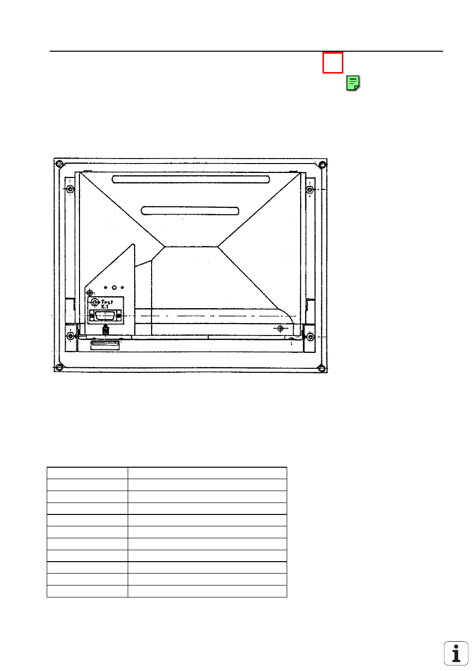
6.4 Connectors on the Visual Display Units
6.4.1 Connectors on the Visual Display Unit BE 212
6.4.1.1 Connector Designation
6.4.1.2 Pin Layout
X1: Connection to the Logic Unit (LE)
Flange socket with male insert (15-pin)
Pin No.
Signal
1 and 8
0V supply
2 and 4
+ 12 V supply
3,5,6,7
not assgined
9
V SYNC
10
H SYNC
11
not assigned
12
0V signal
13
VIDEO
14,15
not assigned
housing
external shield = housing
Advertising
This manual is related to the following products: