5 finished p a rt cont our – HEIDENHAIN CNC Pilot 4290 User Manual
Page 253
HEIDENHAIN CNC PILOT 4290
241
”Circular overlay” parameters
X, Z:
Starting point – Position of the first overlay element
α:
Starting point as angle (reference: one line running parallel to
the Z axis and through the center of the selected arc)
Position:
■
Original position: Inserts the overlay contour ”as it is” into
the support contour (see section 1. in the figure).
■
Normal position: rotates the overlay contour about the
normal position: The overlay contour is rotated by the angle of
the ”overlay point” and is inserted into the support contour
(see section 2. in the figure).
Q:
Number of overlay elements
β:
End point - position of the last element to be superimposed
(reference: a line segment running parallel to the Z axis and
intersecting the midpoint of the selected arc)
βe:
Angle between the first and last overlay element
βi:
Angle between the individual overlay elements
The direction of rotation according to which the overlay contours
are arranged corresponds to the direction of rotation of the supporting
contour element.
The reference point of the contour to be superimposed is
positioned on the ”point of overlay.”
6.5 Finished P
a
rt
Cont
our
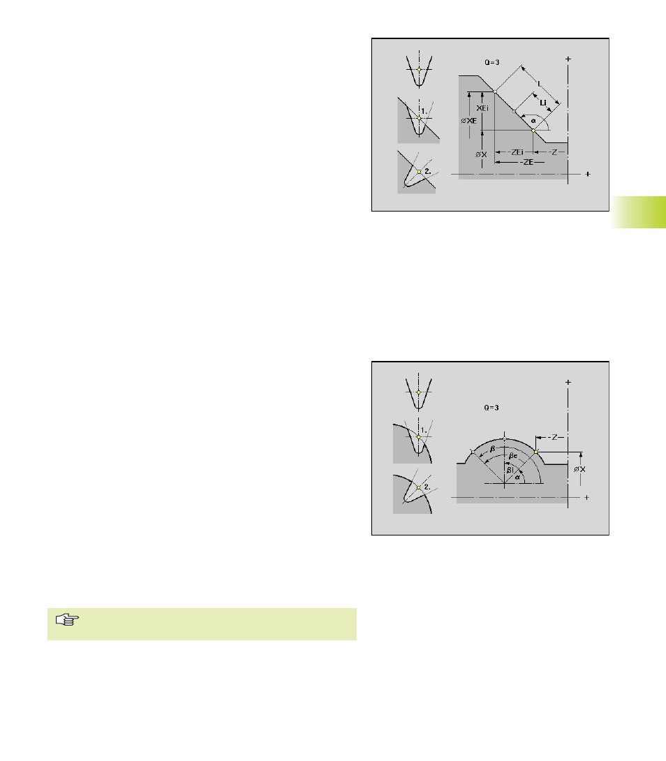
”Linear overlay” parameters
X, Z:
Starting point – Position of the first overlay element
Position:
■
Original position: Inserts the ”original” overlay contour in
the supporting contour (see Help graphic ”1.”).
■
Normal position: Rotates the overlay contour about the
pitch angle of the supporting contour element and inserts it
then in the supporting contour (see help graphic ”2.”).
Q:
Number of overlay elements
XE, ZE: End point – Position of the last overlay element
XEi, ZEi: Incremental end point
L:
Distance between the first and last overlay element
Li:
Distance between the overlay elements
α:
Angle – default: Angle of the supporting contour element