Pilz PZE 9 24VAC 8n/o 1n/c User Manual
Page 4
- 4 -
Technical Data
Operating Voltage U
B
Voltage Tolerance
Power Consumption for U
B
AC
Power Consumption for U
B
DC
Residual Ripple DC
Frequency Range AC
Safety contacts (n/o)
Auxilliary contact (n/c)
Utilization category
to EN 60947-4-1
AC1 Safety contacts
AC1 Auxilliary contacts
DC1 Safety contacts
DC1 Auxilliary contacts
Utilization category
to EN 60947-5-1
AC15 Safety contacts
AC15 Auxilliary contacts
DC13 Safety contacts
DC13 Auxilliary contacts
(DC13: 6 cycles/min)
Contact material
Charactéristiques techniques
Tension d’alimentation U
B
Plage de la tension d’alimentation
Consommation pour U
B
AC
Consommation pour U
B
DC
Ondulation résiduelle DC
Fréquence AC
Contacts de sécurité (F)
Contacts d'info (O)
Catégorie d’utilisation
d'après EN 60947-4-1
AC1 Contacts de sécurité (F)
AC1 Contacts d'info (O)
DC1 Contacts de sécurité (F)
DC1 Contacts d'info (O)
Catégorie d’utilisation
d'après EN 60947-5-1
AC15 Contacts de sécurité (F)
AC15 Contacts d'info (O)
DC13 Contacts de sécurité (F)
DC13 Contacts d'info (O)
(DC13: 6 manoeuvres/min)
Matériau contact
AC: 24, 42, 48, 110 - 120,
230 - 240 V
DC: 24 V
-15 % / +10 %
7 VA
3,5 W
160 %
50 - 60 Hz
8
1
240 V/0,01 ... 8 A/2000 VA
400 V/0,01 ... 5 A/2000 VA
240 V0,01 ... 2 A/500 VA
24 V/0,01 ... 8 A/200 W
24 V/0,01 ... 2 A/50 W
230 V/5 A
230 V/2 A
24 V/7 A
24 V/2 A
AgSnO
2
+ 0,2 µm Au
Technische Daten
Versorgungsspannung U
B
Spannungstoleranz
Leistungsaufnahme bei U
B
AC
Leistungsaufnahme bei U
B
DC
Restwelligkeit DC
Frequenzbereich AC
Sicherheitskontakte (S)
Hilfskontakte (Ö)
Gebrauchskategorie
nach EN 60947-4-1
AC1 Sicherheitskontakte
AC1 Hilfskontakte
DC1 Sicherheitskontakte
DC1 Hilfskontakte
Gebrauchskategorie
nach EN 60947-5-1
AC15 Sicherheitskontakte
AC15 Hilfskontakte
DC13 Sicherheitskontakte
DC13 Hilfskontakte
(DC13: 6 Schaltspiele/Min.)
Kontaktmaterial
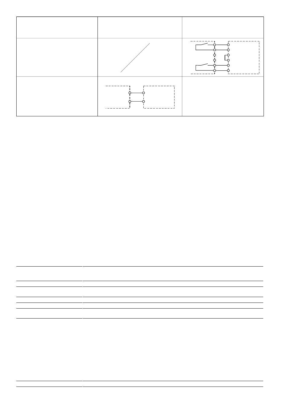
Rückführkreis: Y1 und Y2 sind Rückführ-
kreiseingänge des Grundgeräts/
Feedback loop: Y1 and Y2 are feedback
loop inputs on the base unit/
Boucle de retour : Y1 et Y2 constituent les
entrées de boucle de retour de l’appareil de
base
PZE
Y2
Y1
Y2
Y1
Eingangskreis/
Input circuit/Circuit d’entrée
K1
K2
U1
Y4
Y3
PZE
U2
Einkanalige Ansteuerung
Single Channel control
Commande par un canal
Zweikanalige Ansteuerung
Two channel control
Commande par deux canaux
mit Querschlußerkennung
with short-circuit recognition
avec détection des courts-circuits
Ablauf
Das Gerät ist eingeschaltet, wenn
• die Versorgungsspannung anliegt (LED
"Power" leuchtet)
• die Eingangskreise geschlossen sind
Die Sicherheitskontakte 13-14, 23-24, ...,
83-84 sind geschlossen und die LEDs "Ch.
1" und "Ch. 2" leuchten. Der Hilfskontakt 91-
92 ist geöffnet. Wird ein Eingangskreis
geöffnet, öffnen die Sicherheitskontakte
13-14, 23-24, ..., 83-84. Der Hilfskontakt
91-92 schließt.
Überprüfung - Fehlerursachen
Durch Schließen bzw. Unterbrechen der
Eingangskreise kann überprüft werden, ob
das Gerät ordnungsgemäß ein- bzw.
ausschaltet.
Das Gerät kann aus Sicherheitsgründen bei
folgenden Fehlern nicht gestartet werden:
• Fehlfunktion der Kontakte:
Da der Kontaktblock mit einem Grund-
gerät verschaltet wird, ist bei verschweiß-
ten Kontakten nach Öffnen des Ein-
gangskreises keine neue Aktivierung
möglich.
• Leitungsunterbrechung, Kurz- oder
Erdschluß (z. B. im Eingangskreis)
To operate
The unit is activated when:
• The operating voltage is supplied (LED
"Power" is illuminated)
• the input circuits are closed
The safety contacts 13-14, 23-24,...,83-84
are closed and the LED's "Ch. 1" and "Ch.
2" are illuminated. The auxilliary contact
91-92 opens. If an input circuit is opened,
the safety contacts 13-14, 23-24,...,83-84
open. The auxilliary contact 91-92 switches
over.
Testing - Fault causes
By closing/interrupting the input circuit, the
correct de-energisation/energisation of the
unit can be tested.
For safety reasons, the unit cannot be
activated if the following faults are present:
• Faulty contact functions:
As the contact block is wired to a base
unit, in the case of welded contacts no
further activation is possible following an
opening of the input circuit.
• Cable break, short-circuit or earth fault
(e.g. in the input circuit).
Mise en oeuvre
L'appareil est activé lorsque :
• la tension d'alimentation est appliquée
(LED "Power" s'allume).
• les canaux d'entrée sont fermés.
Les contacts de sécurité 13-14, 23-24 ,...,
83-84 sont fermés et les LED's de
visualisation "Ch. 1" et "Ch. 2" s'allument.
Le contact d'info. 91-92 est ouvert.Si l' un
des circuits d'entrée est ouvert, les contacts
13-14, 23-24,...,83-84 retombent et le
contact d'info. 91-92 se referme.
Vérification-sources d'erreurs
Le bon fonctionnement du relais peut être
vérifié en ouvrant et en refermant les
canaux d'entrée.
Pour garantir la fonction de sécurité, le relais
n'est pas réarmé en cas des défauts
suivants:
• Défaillance d'un contact interne :
En cas de soudage d'un contact interne,
un nouvel réarmement du relais est
impossible (le relais doit être relié à un
appareil de base).
• Coupure d'un canal d'entrée, court-circuit
ou défaut de masse dans les canaux
d'entrée sont détectés.