Installation of compressed air, Operator’s manual, Ff20 – Watson-Marlow FF20 User Manual
Page 7
Advertising
OPERATOR’S MANUAL
Machine Type:
FF20
FF20 OM 1.01 EN.doc
Page 7 of 24
Fig. 2
Attach the filling stand Fig. 2 to the large hole in the frame cover plate. The spacing bush
must be positioned between the cover plate and the cheek, and the nut fixes the stand.
4.2.
Installation of compressed air.
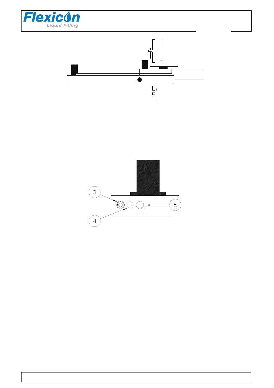
Fig. 3
Compressed air (5 - 7 bar) is connected to the input on FlexFeed 20 (3).
All exhaust air from FlexFeed 20 is gathered and released via the filter (4) which can be
replaced by the supplied hose connection, so that all exhaust air can be expelled from the
room.
If using a dumping needle, the air supply for this can be taken from the outlet (D) in fig. 1.
Advertising