D.4.2 margin requirements, D.4.3 carrier-in-carrier latency – Comtech EF Data CDM-750 User Manual
Page 267

CDM-750 Advanced High-Speed Trunking Modem
Revision 2
Appendix D
MN-CDM750
D–9
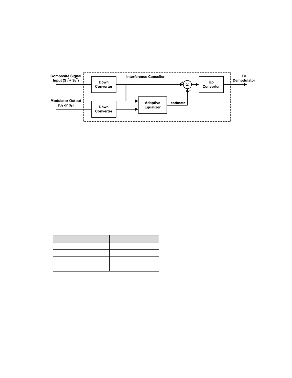
signal. The interference cancellation algorithm uses the composite signal and the local copy of
S1 to estimate the necessary parameters of scaling (complex gain/phase), delay offset and
frequency offset. The algorithm continuously tracks changes in these parameters as they are
generally time‐varying in a satellite link.
Figure D-6. Carrier-in-Carrier Signal Processing Block Diagram
The resulting estimate of the unwanted interfering signal is then subtracted from the composite
signal. In practical applications, the estimate of the unwanted signal can be extremely accurate.
Unwanted interfering signal suppression of 30 dB or more has been achieved in commercial
products with minimal degradation of the demodulator performance.
D.4.2 Margin Requirements
Depending on the product, typical interfering signal cancellation is 28 to 35 dB. The residual
interfering signal appears as noise, causing a slight degradation in received Es/No. To
compensate for the residual noise, a small amount of additional link margin is required to
improve the Es/No and maintain the QEF performance. Margin requirements depend on the
product, modulation and power ratios; for the CDM‐750, these additional margin requirements
are as follows:
Modulation
Nominal Margin*
QPSK 0.3
dB
8PSK 0.3
dB
16APSK 0.6
dB
32APSK 1.0
dB
* Equal power and equal symbol rate for the interfering carrier and the desired carrier, i.e., 0 dB
CnC ratio. Measured at IF with AWGN, +7 dBc Adjacent Carriers, 1.3 spacing.
D.4.3 Carrier-in-Carrier Latency
DoubleTalk Carrier‐in‐Carrier has no measurable impact on circuit latency.