HEIDENHAIN iTNC 530 (340 49x-04) ISO programming User Manual
Page 357
HEIDENHAIN iTNC 530
357
8.3 Cy
cles f
o
r Dr
illing, T
a
pping and Thr
ead Milling
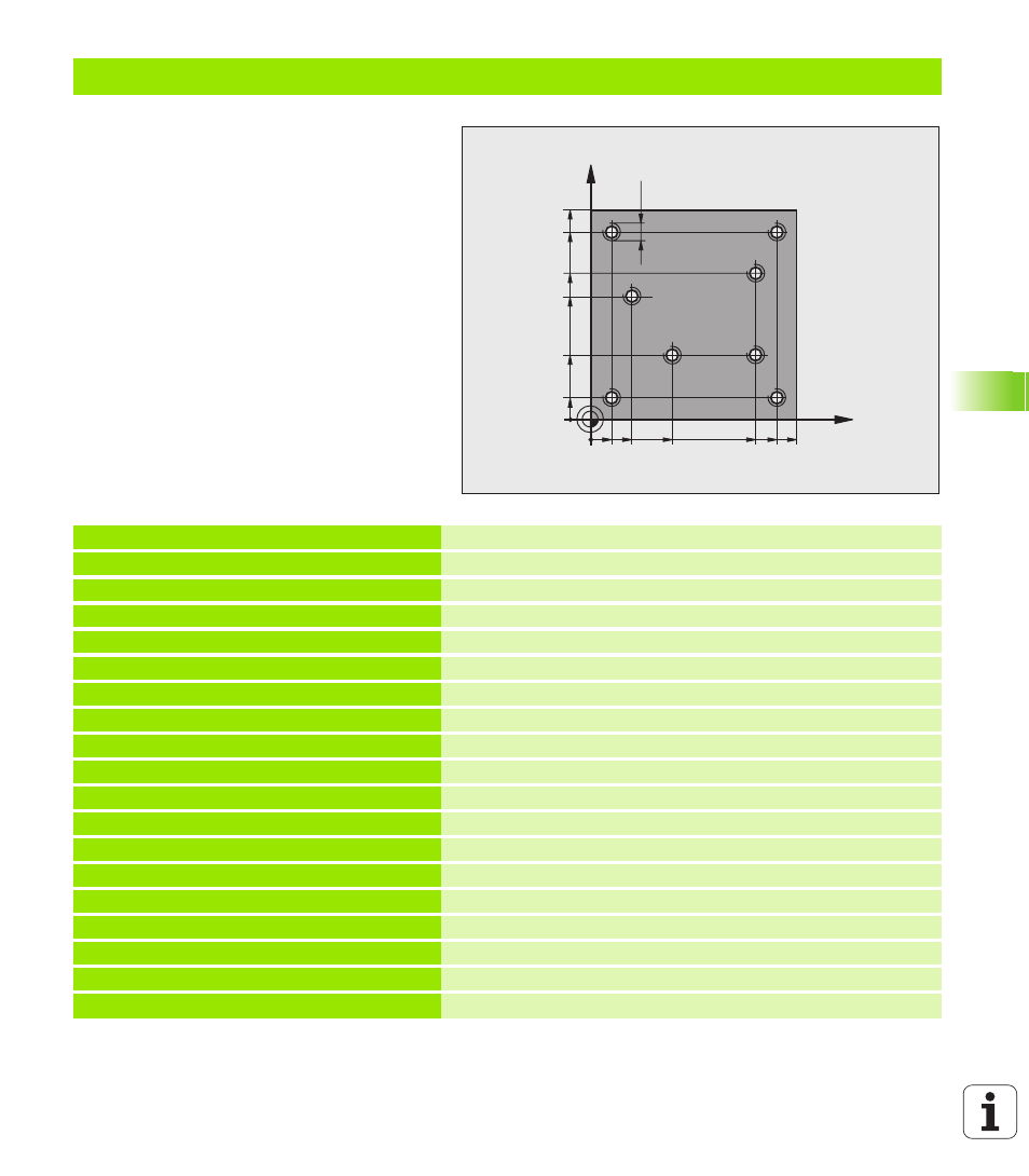
Example: Calling drilling cycles in connection with point tables
The drill hole coordinates are stored in the point
table TAB1.PNT and are called by the TNC with
G79 PAT.
The tool radii are selected so that all work steps
can be seen in the test graphics.
Program sequence
Centering
Drilling
Tapping
%1 G71 *
N10 G30 G17 X+0 Y+0 Z-20 *
Definition of workpiece blank
N20 G31 G90 X+100 Y+100 Z+0 *
N30 G99 T1 L+0 R+4 *
Tool definition of center drill
N40 G99 T2 L+0 R+2.4 *
Define tool: drill
N50 G99 T3 L+0 R+3 *
Tool definition of tap
N60 T1 G17 S5000 *
Tool call of centering drill
N70 G01 G40 Z+10 F5000 *
Move tool to clearance height (Enter a value for F.
The TNC positions to the clearance height after every cycle.)
N80 %:PAT: “TAB1“ *
Defining point tables
N90 G200 DRILLING
Cycle definition: CENTERING
Q200=2
;SET-UP CLEARANCE
Q201=-2
;DEPTH
Q206=150
;FEED RATE FOR PLNGNG
Q202=2
;PLUNGING DEPTH
Q210=0
;DWELL TIME AT TOP
Q203=+0
;SURFACE COORDINATE
0 must be entered here, effective as defined in point table
Q204=0
;2ND SET-UP CLEARANCE
0 must be entered here, effective as defined in point table
Q211=0.2
;DWELL TIME AT DEPTH
X
Y
20
10
100
100
10
90
90
80
30
55
40
65
M6