HEIDENHAIN IK 5394-3D User Manual
Page 504

6 - 54
Chapter 6 System Setup
Specifying part view tiles
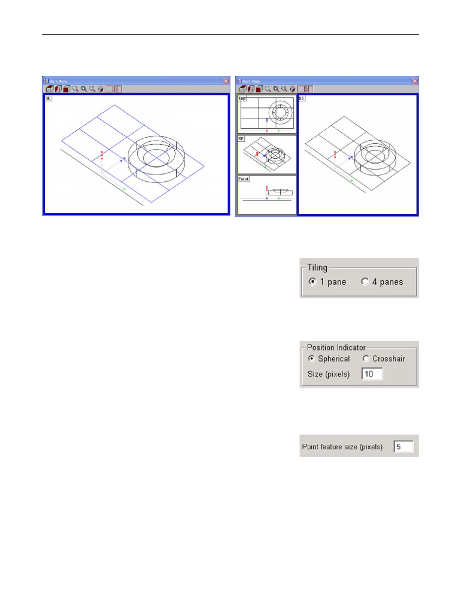
Parts can be displayed in single and multiple tile views.
The orientation of the part in each tile is selected by the user in the Part View
toolbar, and is independent of part orientations in other tiles.
Click the radio button of the desired tile
view in the Tiling group.
Specifying probe position indicator type
The default probe indicator shown in the Part View window during program
execution can be specified as Spherical (asterisk) or Crosshairs.
Click the radio button of the desired
probe position indicator in the Position
Indicator group, and then enter the de-
sired indicator size.
Specifying point size
The displayed size of measured and constructed points can be specified in pix-
els.
Enter the desired size for displaying point
features into the Point feature... field.