Configuration procedure – H3C Technologies H3C WX3000E Series Wireless Switches User Manual
Page 257
Advertising

243
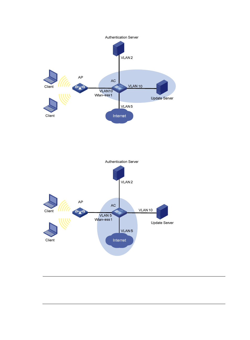
Figure 117 Network diagram
As shown in
, after the host passes the authentication and logs in, the client is added to VLAN
5. In this case, the client and WLAN-ESS 1 are both in VLAN 5, and therefore the client can access the
Internet.
Figure 118 Network diagram
Configuration procedure
NOTE:
•
Use the iNode client in this example. The client that comes with Windows does not support the function.
•
This example covers only some of the required AAA and RADIUS configuration commands. For more
information, see "Configuring AAA."
Advertising
This manual is related to the following products:
- H3C WX5500E Series Access Controllers H3C WX3500E Series Access Controllers H3C WX2500E Series Access Controllers H3C WX6000 Series Access Controllers H3C WX5000 Series Access Controllers H3C LSWM1WCM10 Access Controller Module H3C LSUM3WCMD0 Access Controller Module H3C LSUM1WCME0 Access Controller Module H3C LSWM1WCM20 Access Controller Module H3C LSQM1WCMB0 Access Controller Module H3C LSRM1WCM2A1 Access Controller Module H3C LSBM1WCM2A0 Access Controller Module H3C WA3600 Series Access Points H3C WA2600 Series WLAN Access Points H3C S10500 Series Switches H3C S5800 Series Switches H3C S5820X Series Switches H3C S12500 Series Switches H3C S9500E Series Switches H3C MSR 5600 H3C MSR 50 H3C MSR 3600 H3C MSR 30 H3C MSR 2600 H3C MSR 20-2X[40] H3C MSR 20-1X H3C MSR 930 H3C MSR 900 H3C SR8800 H3C SR6600-X H3C SR6600 H3C SecPath F5020 H3C SecPath F5040 H3C VMSG VFW1000