4 cdi-60 hssi interface, 1 cdi-60 hssi interface transmit clocking, 2 cdi-60 hssi interface receive clocking – Comtech EF Data CDM-700 User Manual
Page 137: Figure 8-4. cdi-60 hssi data interface

CDM-700 High Speed Satellite Modem
Revision 5
Clock Modes
MN/CDM700.IOM
8.4
CDI-60 HSSI Interface
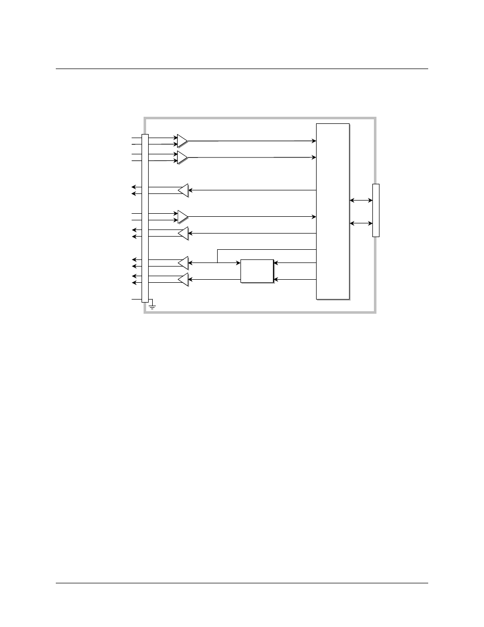
The CDI-60 HSSI Interface has a single rate programmable port. Figure 8-4 shows the interface.
Processor
Mux /
Demux
PLL
Rx
Buffer
Interface
Loopback
Control
Processor
Mux /
Demux
PLL
Rx
Buffer
Interface
Loopback
Control
Modem
Interface
Clk
&
Data
μC
HSSI Interface
TT
SD
ST
Common
J1
Rx Buffer Clock
Rx Data
5
0
P
in H
S
SI Fem
a
le
TA
CA
(RTS)
(CTS)
Tx Clock Input (External)
Tx Data
Output Clock (Rate Programmable)
RT
RD
Rx Buffer
Rx Buffer
Rx-Sat Clock
Figure 8-4. CDI-60 HSSI Data Interface
8.4.1 CDI-60 HSSI Interface Transmit Clocking
TT is the transmit clock source for the HSSI interface, and it is sent in conjunction with the data,
SD, by the DTE to the modem. The data interface dejitters and phase locks to the TT clock rate.
Internal clocking where ST is supplied to the DTE and TT is not returned to the modem is not
allowed. Programming the Tx data rate at the interface programs the clock rate for ST sent to the
DTE. When operating with HSSI interfaces always send ST to the DTE and assure that TT
derived from ST is delivered to the DCE.
Rx Loop-Timed where ST is programmed to a rate derived from the Rx-Sat clock from the
satellite is not available. For loop timed operation disconnect ST at the DTE and connect RT from
the DCE (modem) to both RT and ST at the DTE.
8.4.2 CDI-60 HSSI Interface Receive Clocking
When the Rx Buffer is disabled the receive clock is the Rx-Sat. In this mode make sure the Rx
Buffer is set to minimum to reduce latency.
8–5