5 p a th cont ours—p o lar coor dinat e s – HEIDENHAIN iTNC 530 (340 49x-01) ISO programming User Manual
Page 198
198
6 Programming: Programming Contours
6.5 P
a
th Cont
ours—P
o
lar Coor
dinat
e
s
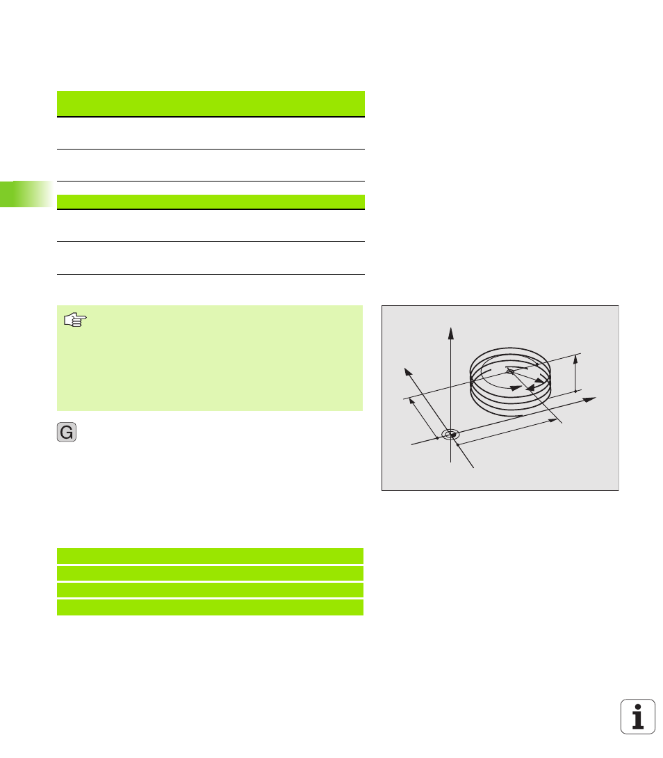
Shape of the helix
The table below illustrates in which way the shape of the helix is
determined by the work direction, direction of rotation and radius
compensation.
Programming a helix
8
Polar coordinates angle H: Enter the total angle of tool
traverse along the helix in incremental dimensions.
After entering the angle, specify the tool axis with
an axis selection key.
8
Enter the coordinate for the height of the helix in
incremental dimensions.
8
Enter the radius compensation G41/G42 according to
the table above.
Example NC blocks: Thread M6 x 1 mm with 5 revolutions
Internal thread
Work
direction
Direction
Radius
comp.
Right-handed
Left-handed
Z+
Z+
G13
G12
G41
G42
Right-handed
Left-handed
Z–
Z–
G12
G13
G42
G41
External thread
Right-handed
Left-handed
Z+
Z+
G13
G12
G42
G41
Right-handed
Left-handed
Z–
Z–
G12
G13
G41
G42
Always enter the same algebraic sign for the direction of
rotation and the incremental total angle G91 H. The tool
may otherwise move in a wrong path and damage the
contour.
For the total angle G91 H, you can enter a value from
–5400° to +5400°. If the thread has more than 15
revolutions, program the helix in a program section repeat
(see “Program Section Repeats” on page 418)
N120 I+40 J+25 *
N130 G01 Z+0 F100 M3 *
N140 G11 G41 R+3 H+270 *
N150 G12 G91 H-1800 Z+5 *
Y
X
Z
25
40
5
270°
R3
CC
12