Lynx Studio LT-TB Thunderbolt User Manual
Page 29
29
External/2: Clock signal from BNC WORDCLOCK connector at half the sample rate
External/4: Clock signal from BNC WORDCLOCK connector at one quarter the sample rate
AES A: Clock signal from the Digital In 1-8 Inputs (Digital in 1-4 with Aurora 8)
AES B: Clock signal from the Digital In 9-16 Inputs (Digital in 5-8 with Aurora 8)
If the selected Preferred Clock Source is not also displayed as the Current Source in the
SAMPLE CLOCK section of the Adapter page, it would be for one of the following reasons:
1. The selected source is not present or the connected device is not generating a valid clock
signal. In these cases, the Aurora will operate from its internal clock until a valid clock signal
is connected to the selected clock source.
2. The selected clock source is generating a sample rate outside of the Aurora’s usable range
(i.e. 22kHz). This can be corrected by setting the clock source to a supported sample rate
(44.1kHz, 48kHz, 88.2kHz, 96kHz, 176.4kHz, 192kHz).
3. The Clock Source was selected when the Aurora was being accessed by some software
application. In this case, the Preferred Clock Source will become the Current Source when
the card is no longer being accessed. If “Allow Clock Change if Active” is selected from the
Lynx Mixer Settings > Advanced menu, then a new Preferred Clock Source can become the
Current Source while the card is being accessed from a software application.
Analog Trims
The Aurora’s Input and Output Trims can be switched between +4dBu (Pro Level) and -
10dBV (Consumer Level) in groups of four channels. +4dBu is the default for all inputs and
outputs. Switching to -10dBV is done to accommodate a piece of consumer gear (cassette
deck, stereo receiver, etc) or a Pro Audio device that happens to have very low signal level.
The VT model of the Aurora does not have fixed Trims, instead it relies on Trim Pots that are
part of the Aurora mainboard. With a VT model, the TRIM values will be grayed out. For
more information about Aurora Trims, see the Aurora User’s Manual, page 7.
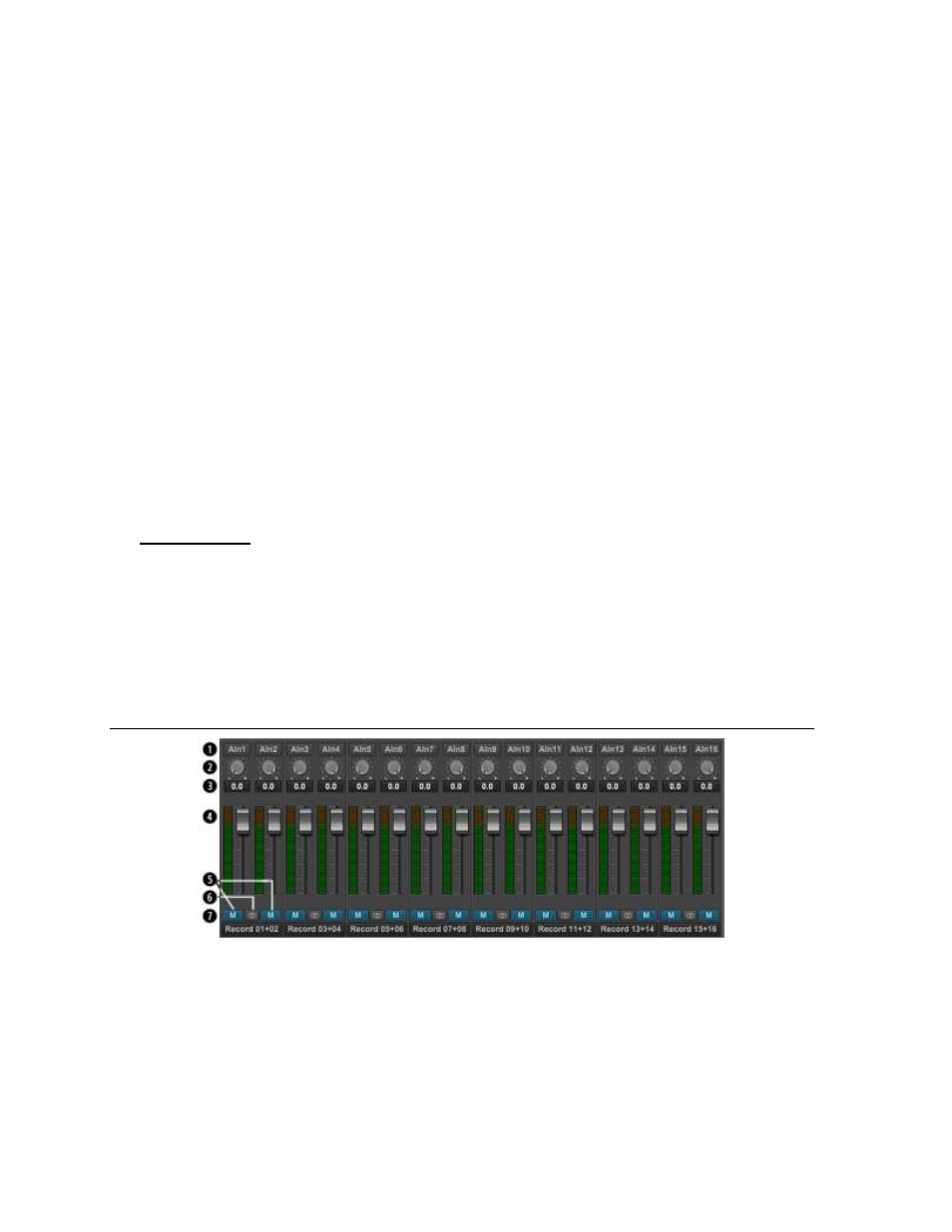
7.3.3 Record Section
The top row of faders on the Main Screen is the Record Section of the Lynx Mixer. The
purpose of this section is to show input signal meter activity, allow assignment of physical
inputs to record devices within the operating system, and manage the levels, routing, and pan
positions of input signals being monitored through Aurora outputs.
The number of faders that appear will be relative to the channel mode that the unit is
operating in. In 16-channel mode, there will be 8 stereo Record Devices. In 24-channel mode
there will be 12 stereo Record Devices, and in 32-channel mode there will be 16. This