Lynx Studio LT-TB Thunderbolt User Manual
Page 36
36
The METERS in the Outputs section show the level strength of the signals at the associated
output. The Meters are post-fader, so there will be reduction in Meter level as the signal is
attenuated.
Mutes
The “M” Icon below the fader is for the Mutes. This switch Mutes or UnMutes the associated
output.
When the “M” button is blue like this
, then the Mute is ON, and no signal will pass to the
selected output. When the “M” button is gray, like this
, then the Mute button is OFF, and
signal CAN pass to the selected output.
Channel Link
In between the two Mute buttons for a pair of Inputs, is the channel link control:
. This
control toggles the linked state for a pair of faders and mutes. If two channels ARE linked,
then moving the fader for one of them will move both channels. Similarly, if one is muted
then both will mute. If the faders between the channels are offset, when one is moved the
other will snap to the same position. The linked state also impacts the Pan controls. If one
pan pot is moved to the left the other will move a corresponding amount to the right. For
instance, if the left pot is set to -25, the right channel will pan to +25.
Linked is the default state for pairs of inputs. To “un-link” a pair, click on the link icon and it
will change to a single circle:
. In this state, the mute, fader and pan controls operate on a
single channel independently.
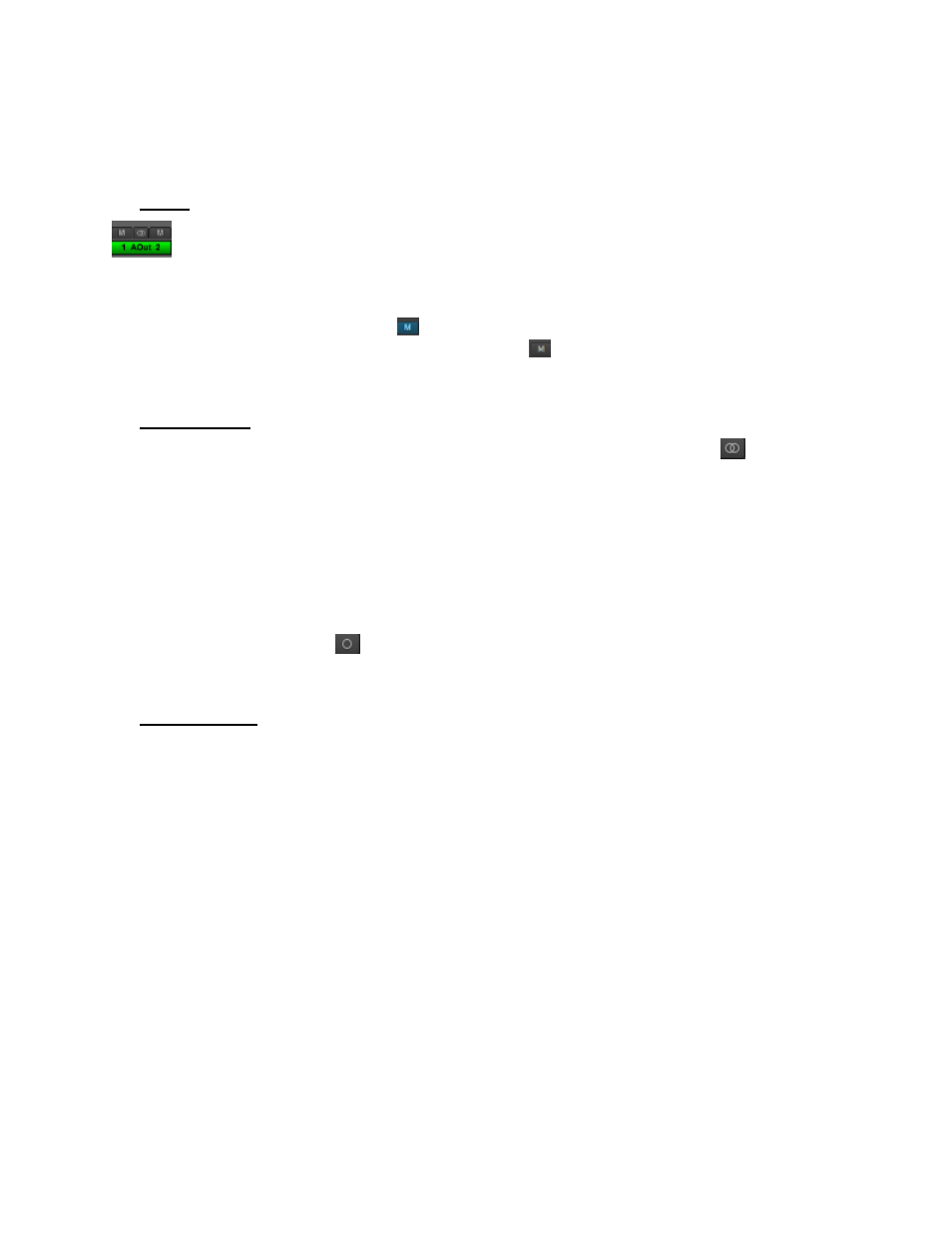
Output Button
This identifies the Outputs that are applicable to the fader and mute controls, and is also used
to facilitate routing. As mentioned, the Lynx Mixer uses an Output oriented approach to
routing. Clicking on an Output button, “selects” that output for sources to be assigned to it.
When selected, the button is green. In this state, sources from both the Record and Play panes
can be un-muted, thereby set to stream to the “selected” output.
In the Mixer’s default state, each output has a play device routed to it. For Analog Output
1+2 it is Play 1+2, for analog output 3+4 it is Play 3+4, etc. For Digital Output 1+2 with an
Aurora16, it would be Play 17+18. With an Aurora 8, Digital Out 1+2 would default to Play
9+10.
To add sources to an output, click an output button to select it and it will turn green. Then un-
mute Record and/or Play sources from the Record and Play Panes. Signals from those
sources will now stream to that output. When multiple sources are assigned to a single
output, it is often necessary to attenuate the individual sources to prevent excessive level
from causing distortion to the output.